A few days ago I managed to brick my Compaq Mini 311 netbook by mistakenly flashing the wrong BIOS image. The computer only switched on the CPU fan for a moment when I pressed the Power on button, then it switched off, nothing worked, no lights were on.
Since the netbook was working perfectly well before the BIOS update I immediately knew that the wrong BIOS image was at fault. However, flashing the correct image required the netbook to start up correctly in some kind of an operating system, which, without a proper BIOS, is not possible. Not even the Win+B combination worked.
Luckily, not all is lost, as all it needed was a correct BIOS, which I could easily download from the manufacturer’s web site.
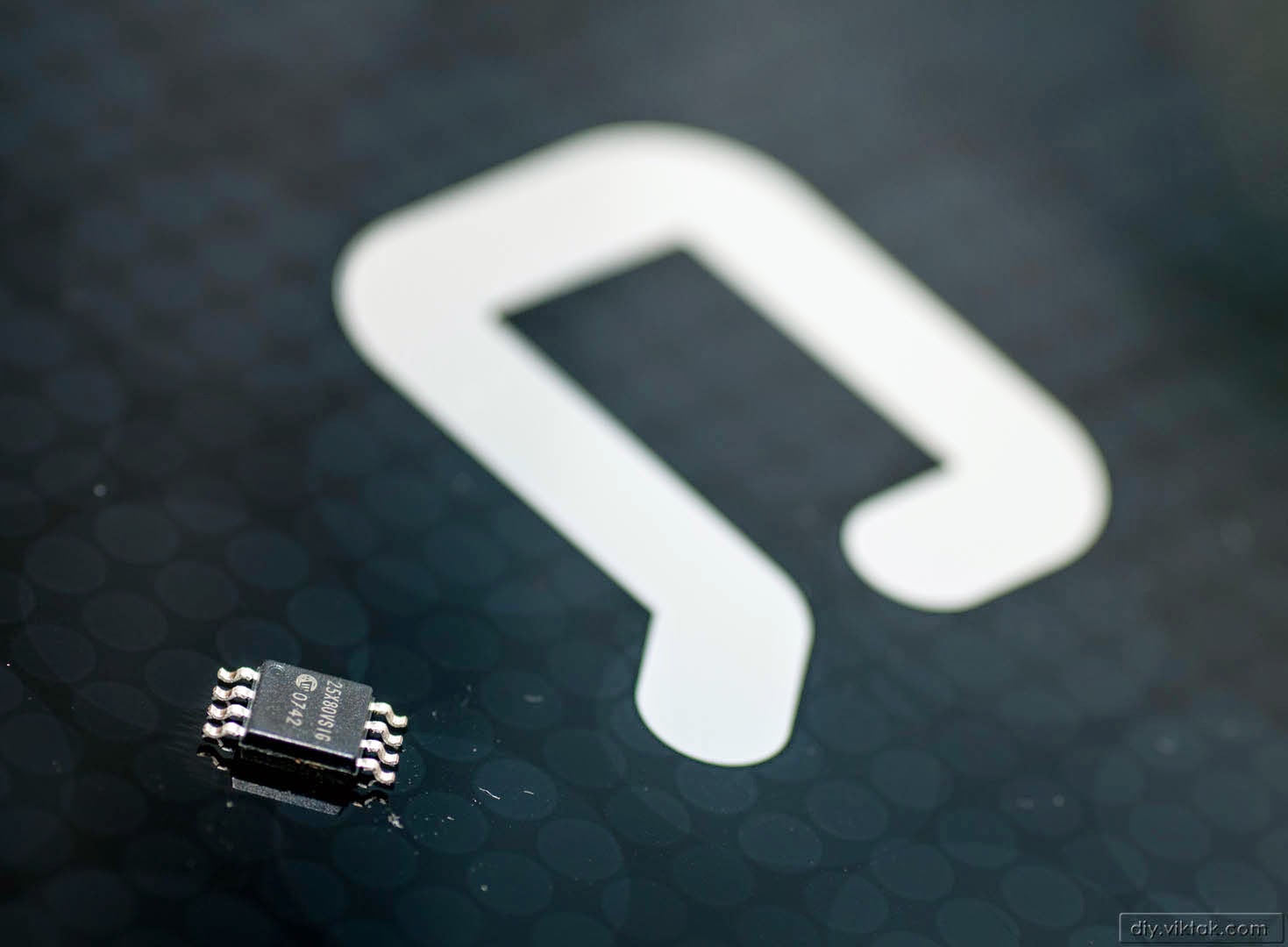
Yes, it’s a Compaq Mini 311 netbook. I prepared a replacement chip loaded with the correct BIOS. Later it turned out that the original chip was not destroyed by the procedure I put it through.
Once I had to open the laptop to fix it I decided to take this opportunity to explore the options there are for fixing the broken BIOS and compile my findings in this article. In the process I tried all of the methods described below, some on the actual laptop I fixed eventually, some on (really-really) dead motherboards.
There are several ways of getting the right BIOS back in the computer – in the following I am going to present a number of ways to get your laptop back on its feet. There are probably more ways to do it, but this should be a good starting point for someone in the same shoes as I was.
General information
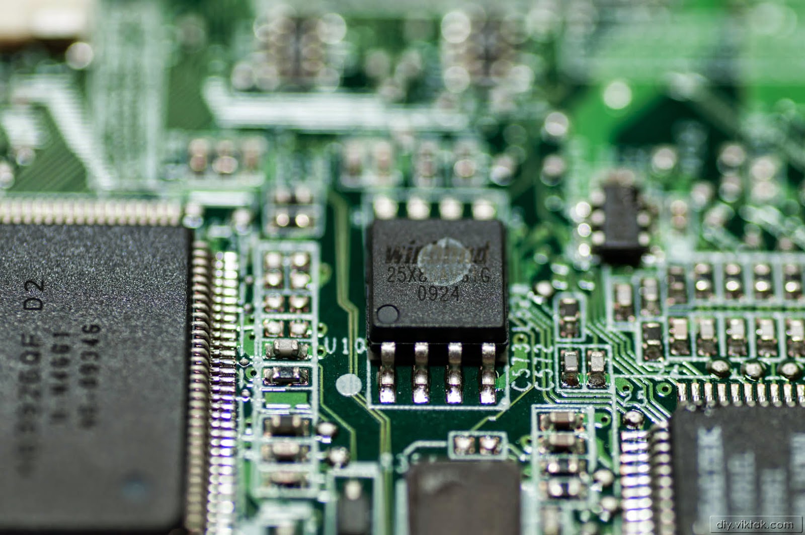
Most fairly recent laptops have their BIOS in a serial EEPROM with an SPI interface on the motherboard. Its location varies, but since it is the only EEPROM on the motherboard, after a few minutes of visual inspection it is easy to reveal it. In some laptops it’s covered by a black sticky tape which needs to be removed temporarily to get access to the chip. These EEPROMS are usually 1024kB (1MB) or 2048kB(2MB) in size. They come from various chip manufacturers, like Winbond, STM, Microship, etc. Not to confuse with BIOS (firmware) manufacturers, i.e. Phoenix, AMI, Award, etc. The product number is printed on the chip and is something like this: 25xx80 (1MB) or 25xx160 (2MB). There may be some extra letters in the front or at the end that are all important when you select a replacement chip, but for the purpose of finding the chip on the motherboard they are not relevant.
Getting access to the BIOS chip
It is of utmost importance that before attempting to access the BIOS chip on the motherboard we disconnect any power source to the motherboard. This includes not only the power supply and possible batteries, but you shouldn’t forget about the CMOS battery, which is usually a small button cell somewhere on the motherboard. I even recommend to remove any extension boards, etc. that is attached to the motherboard, such as wifi card, bluetooth card, hard disks, etc.
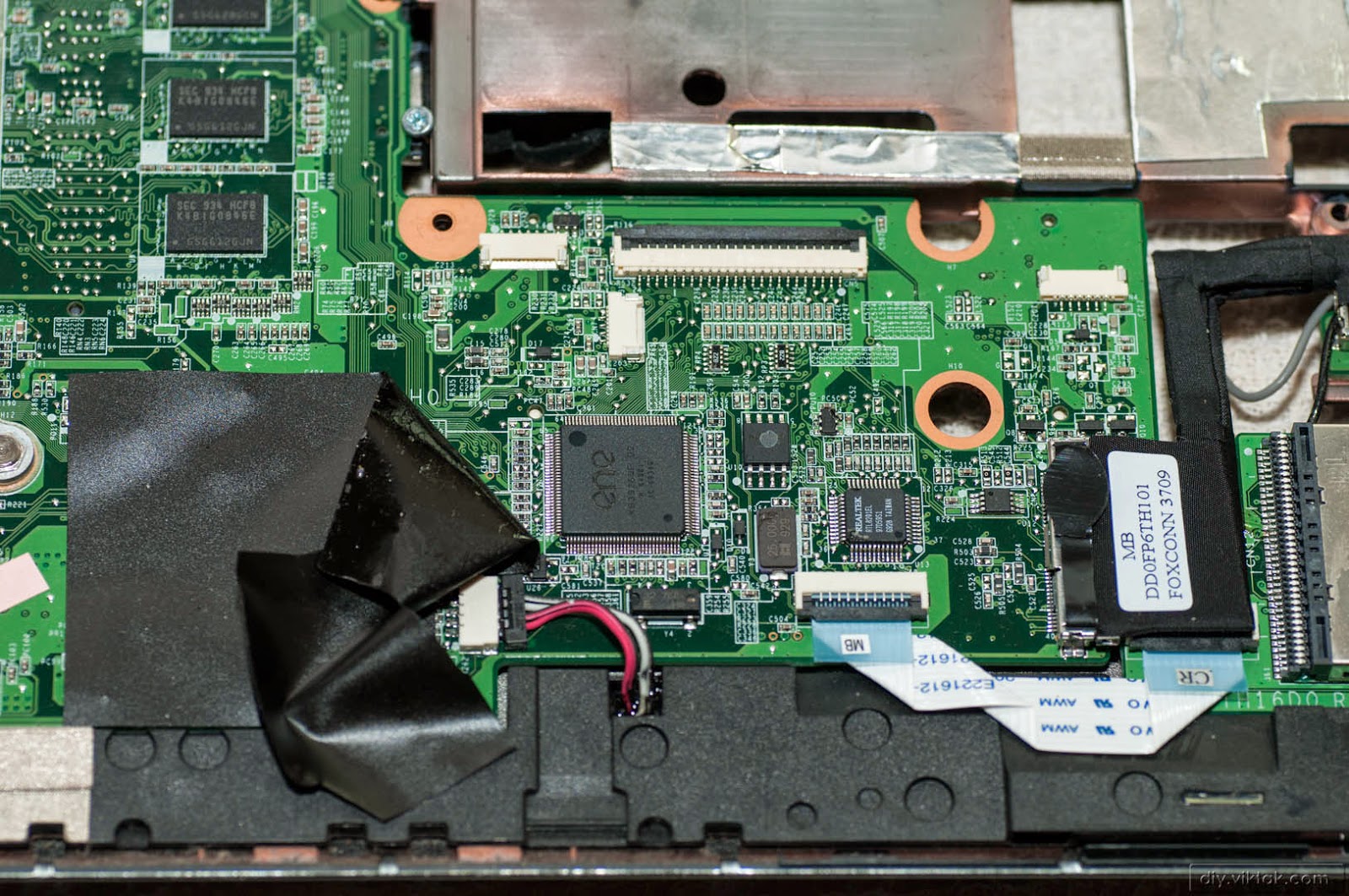
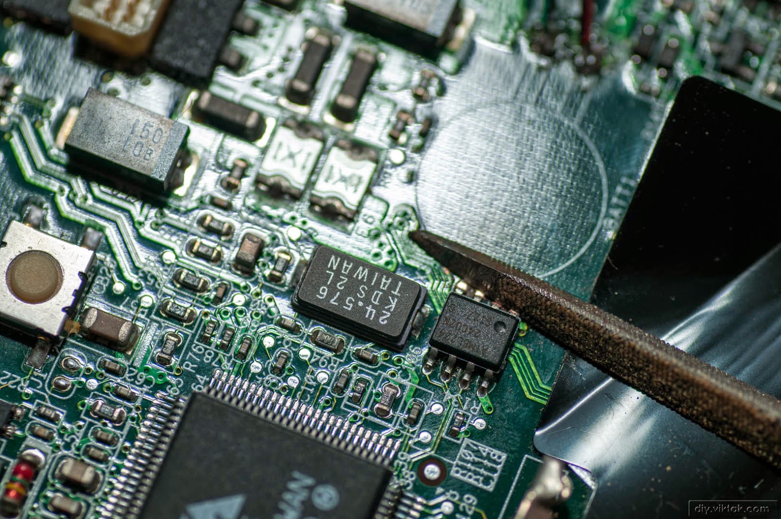
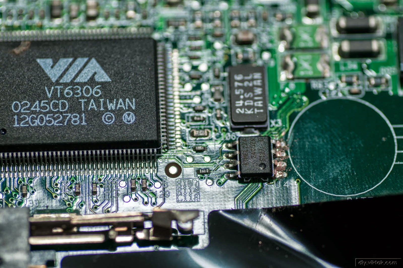
On the Compaq Mini 311 motherboard the BIOS chip was hidden under a layer of black, sticky tape. I folded it back temporarily to get access to my target.
The BIOS chip is a Winbond 25X80AVSIG.
Once we locate the BIOS chip on the motherboard first we need to establish connection to it with an EEPROM programmer (explained later). This can be accomplished in several ways:
Soldering wires directly to the pins of the chip
Using thin (around 30AWG), insulated wires we can connect the chip to the programmer. Since it is easy to create short circuits on the motherboard around the BIOS chip while soldering the wires on and off this method is only advised to people who are experts in precision soldering and they only need to flash their BIOS chips once, then remove the wires.
Using a SOIC test clip to hook on to the BIOS chip
Cheap SOIC clips are readily available on eBay. They are easy and relatively safe to use on the chip that is sitting in the motherboard. This is probably the safest option for most people, although it also has some limitations:
some motherboards are designed in such a way that the SOIC clip does not have enough room around the chip to securely latch on.
some motherboards are designed in such a way that circuitry on the motherboard interferes with the programmer and as a result even with good connection reading and writing the BIOS chip is not possible without removing the chip from the motherboard first.
Removing the BIOS chip from the motherboard
If either of the above cases applies to you, you have to take more drastic measures and you have to remove the BIOS chip from the motherboard for programming. Next, I will show a few ways to do just that.
Safest method: cutting the pins
If you don’t care about saving the chip used in the motherboard (because you have a spare one, duh!) then your safest bet is to use a side clipper tool to cut or use a small file to file away each pin one by one. Be patient, don’t force the pins away from the board as they may bring some of the tracks from the PCB and then you are in real trouble – as far as fixing your computer goes.
Fixing a broken BIOS chip in a Fusitsu-Siemens laptop. Filing away the pins is a slow, painstaking process…
If you went with the “filing away” method don’t forget to clean up the resulting metal dust and shavings from around the motherboard. They can cause short circuits later, when power is re-applied.
Pins on the right are almost gone.
Once all the pins are cut you can use your soldering iron to clean up the remains.
After the above procedure soldering the new chip in place will feel like a breeze. When soldering in the replacement chip pay attention to the orientation – pin #1 is marked on both the old and the new chips, make sure they match.
The specialist method: using hot air
If you have access to a hot air soldering station you can take you can make use it to easily remove the chip. However, this is a fairly dangerous way of retrieving the chip as stray heat from the heat gun can easily de-solder nearby components making a mess and possibly finishing off the computer. It is advised to cover the surrounding areas with a heat resistant tape leaving only the chip to be removed exposed to the heat. Also, you need to make sure to hold the nozzle vertically at all times to reduce the chance of blowing away nearby components. This method requires a high level of expertise and experience in soldering using a hot air. It is easy to make a mess by setting it to too high temperature of too strong airflow (it can easily blow away nearby tiny components such as resistors, capacitors, etc.).
The traditional method: using the good old soldering iron
This method also requires a great deal of experience in soldering. You have to be fast and precise, otherwise you’ll ruin the BIOS chip, the motherboard, or both.
I tend to put a lot of flux on the pins first, to aid working with the solder.
Then I put extra solder on the pins to the point where either side of the chip is one big blob of solder. This helps to distribute heat evenly across the pins, fast.
Then I alternate with the soldering iron between the two sides fast enough so that one side doesn’t cool down while I am warming the other.
With this method I can remove the chip within a few few seconds using a pair of tweezers.
Once the chips is off the board, clean up the pads in preparation for the new chip. If you do it as fast as I did, you can re-use the old chip after it has been re-programmed.
Programming the chip with the new BIOS
Method #1: Using a dedicated EEPROM programmer
There are countless EEPROM programmers available on eBay, some are cheaper, some are better. Most are suitable for our purpose, but before ordering one always make sure your particular EEPROM is supported by the programmer.
I have an old Willem EPROM Programmer for Parallel Port (yes, I said old…). It does support SPI EEPROMS of the 25xxx series: it has a DIP-8 socket to take EEPROMS so you have to come up with a way of connecting the SOIC BIOS chip there. See ideas earlier.
The programmer comes with an application that is used to read/write/etc. the chips. Since each programmer has its own application I am not going into the details on how to use them. Generally, you just select the chip to program, load the new BIOS file and off you go.
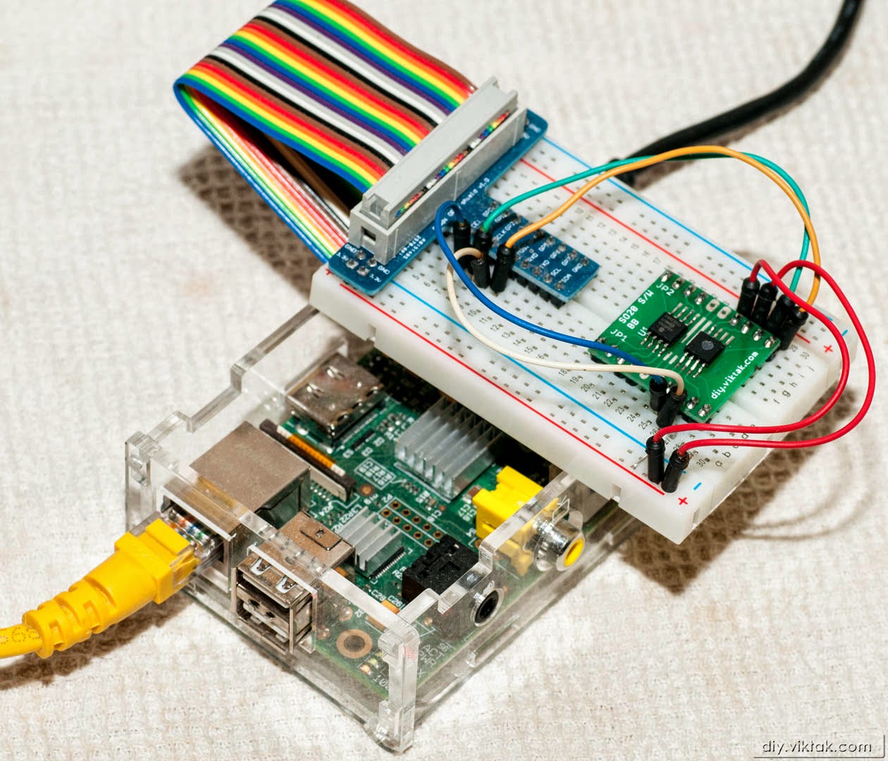
Method #2: Using a Raspberry Pi
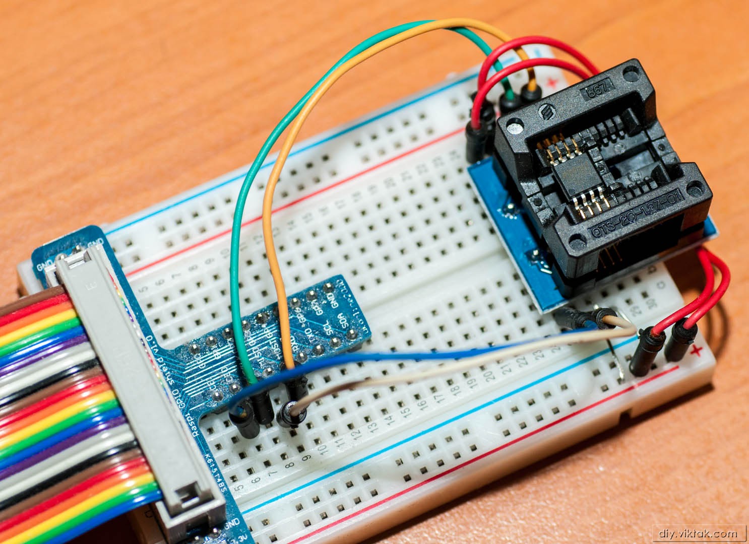
The Raspberry Pi can be very easily turned into an SPI EEPROM programmer as it has a built in SPI interface. I used a cheap breakout board, some jumper wires and a small breadboard, all from eBay. Since the BIOS chip usually comes in a SOIC packaging, I used a SOIC to DIP converter to be able to stick the chip in the breadboard.
The setup
Here is the setup I used:
Using a drop-in SOIC-DIP converter is probably the easiest way to program these tiny chips.The connections can be seen clearly here: The jumper cables are easy to follow. Note the two tiny jumpers on pins #3 (Vcc) and #4 (Gnd).
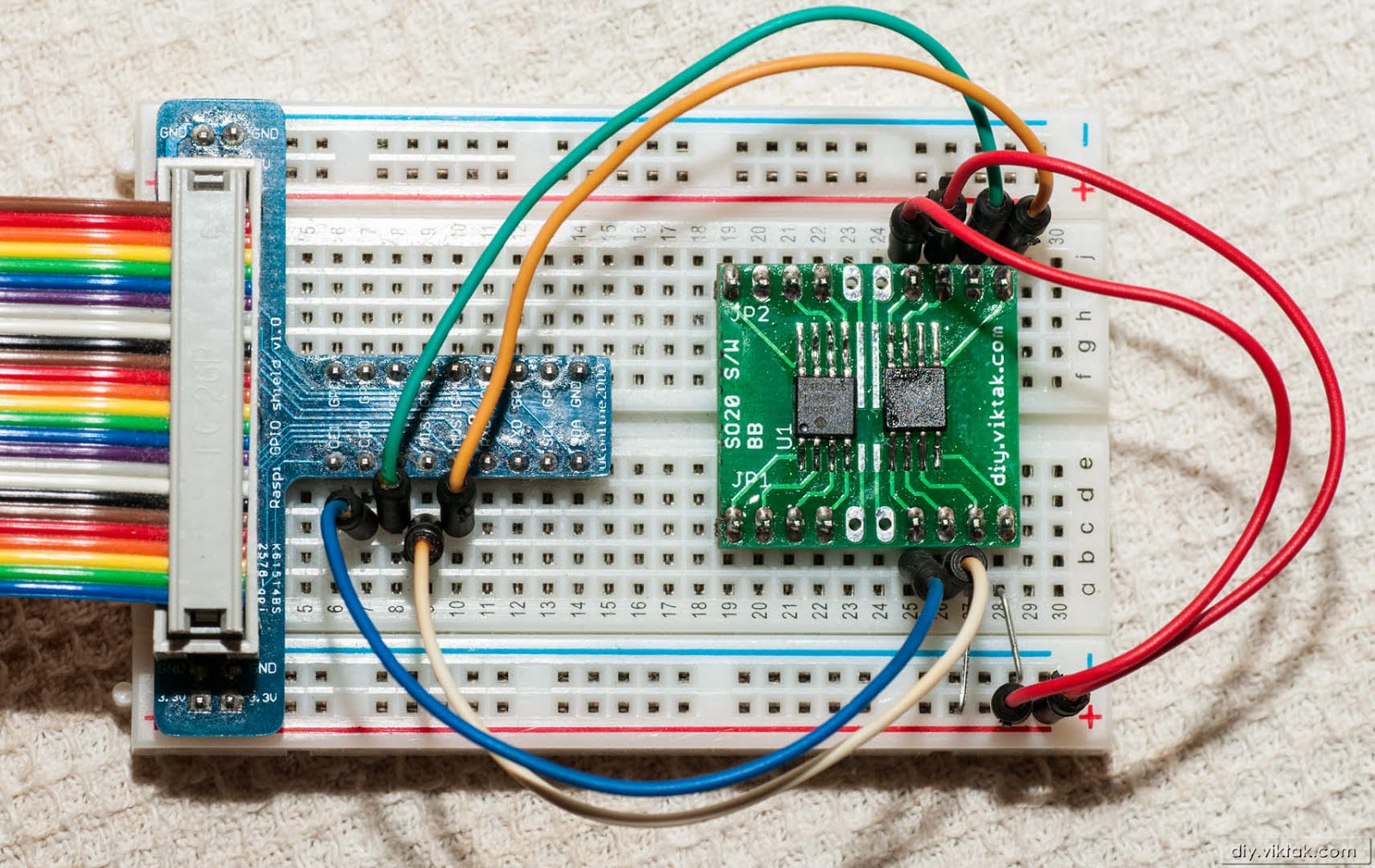
Since I had a few of these chips on stock, I decided to solder one in for my experiments. This way I can also re-use it in other projects.
My SOIC to DIP converter board takes chips of 20pins max, so I decided to put an I2C EEPROM (on the left) as well as an SPI EEPROM (on the right) for experimentation.
For further experiments I used this more permanent rig. It includes both an I2C and an SPI EEPROM.
Everything assembled, ready to go.
Preparing the Raspberry Pi
I used the default Raspbbian Debian Wheezy operating system on the RPi. After a standard installation I used the several steps to be able to use SPI:
1. Make sure the RPi is up to date:
sudo apt-get update sudo apt-get upgrade
2. Create a samba share so that I can copy files easily back and forth from my Windows computer (optional)
sudo apt-get install samba samba-common-bin sudo cp /etc/samba/smb.conf /etc/samba/smb.conf.old sudo /etc/init.d/samba restart sudo smbpasswd -a pi sudo /etc/init.d/samba restart
3. Install the Linux PCI Utilities
sudo apt-get install pciutils-dev
4. Install Flashrom
Flashrom is a utility to do stuff with flash chips. Detailed installation and usage instructions are available on its web site. I simply downloaded the sources and compiled my own binaries:
Download and extract the latest stable release to a directory called flashrom-0.9.7 on the RPi.
Compile and install flashrom:
cd flashrom-0.9.7/ sudo make sudo make install
5. Load the SPI drivers:
sudo modprobe spi_bcm2708sudo modprobe spidev
6. Edit the backlist file so that the SPI module is always loaded every time the RPi starts:
sudo nano /etc/modprobe.d/raspi-blacklist.conf
# blacklist spi and i2c by default (many users don’t need them) #blacklist spi-bcm2708 #blacklist i2c-bcm2708
If everything went OK, the following command will test the hardware connection and detect the chip we connected:
flashrom –p linux_spi:dev=/dev/spidev0.0
The output should be something like this:
flashrom v0.9.7-r1711 on Linux 3.12.20+ (armv6l) flashrom is free software, get the source code at http://www.flashrom.org Calibrating delay loop… OK. Found Winbond flash chip “W25X80” (1024 kB, SPI) on linux_spi. No operations were specified.
To save an old BIOS (as a backup, if yours is still good) use the following command:
flashrom v0.9.7-r1711 on Linux 3.12.20+ (armv6l) flashrom is free software, get the source code at http://www.flashrom.org Calibrating delay loop… OK. Found Winbond flash chip “W25X80” (1024 kB, SPI) on linux_spi. Reading flash… done.
It took about 21 seconds to complete the above command.
To erase the BIOS chip use the following command:
flashrom –p linux_spi:dev=/dev/spidev0.0 -E
flashrom v0.9.7-r1711 on Linux 3.12.20+ (armv6l) flashrom is free software, get the source code at http://www.flashrom.org Calibrating delay loop… OK. Found Winbond flash chip “W25X80” (1024 kB, SPI) on linux_spi. Erasing and writing flash chip… Erase/write done.
It took about 42 seconds to complete the above command.
To upload the new BIOS in the chip use the following command:
flashrom v0.9.7-r1711 on Linux 3.12.20+ (armv6l) flashrom is free software, get the source code at http://www.flashrom.org Calibrating delay loop… OK. Found Winbond flash chip “W25X80” (1024 kB, SPI) on linux_spi. Reading old flash chip contents… done. Erasing and writing flash chip… Erase/write done. Verifying flash… VERIFIED.
It took about 70 seconds to complete the above command.
Method #3: Using a Bus Pirate on a linux system (even a RPi)
If you have a Linux system, you can also use a Bus Pirate to program the chip. The preparations are pretty much the same as in the case of the Raspberry Pi. Obviously, the RPi specific parts should be omitted. Also, all commands need to change a bit to reflect the change of device, so for example, reading the contents of the the chip would go like this:
In the above article I have shown a few ways of getting access to and programming a BIOS chip in most modern laptops/PCs. While this is not a comprehensive list of possible ways, it is a good starting point for people who feel they care able to fix their messed up BOIS chips.
If you have better ways of dealing with a failed BIOS upgrade, please let us all know about it in the comments.