
Introduction
Earlier today I needed an extra of those USB-to-TTL-Serial adapters for a project I am currently working on. Among my spare parts I found an old one, based on the PL-2303HX chip, but when I attached it to my Windows 11 PC, it didn’t seem to work. I remember, a couple of years ago I used it with Windows 10, but to get it to work, I needed to do some workaround as this chip is obsolete and, for some reason, does not work with its own driver (which installs fine). So I went back to digging some more in the part box and quickly found another one, that is based on the FT232RL chip, which is compatible with Windows 11. Great, I was back on track with my project!
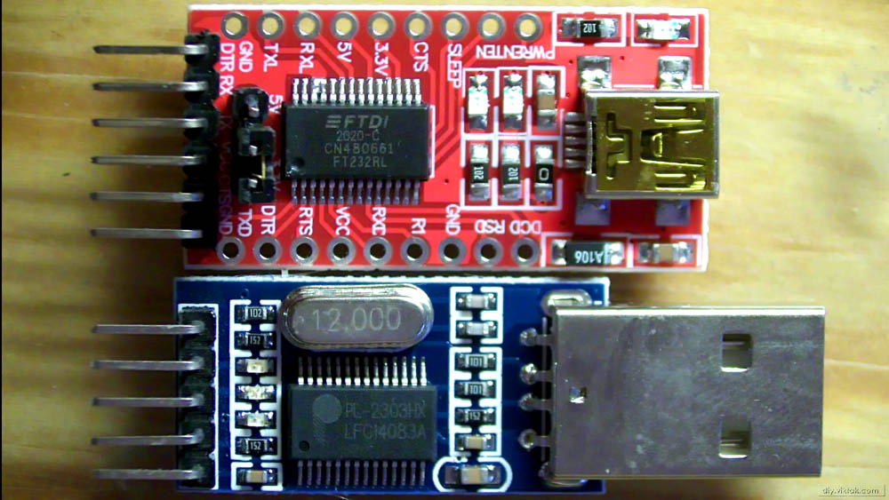
Unfortunately, this adapter has a built-in USB Mini-B socket, which means I need another cable to connect it with the USB hub on my desk. This would mean a meter or so long cable rolled up on my desk, adding to the clutter – unacceptable! I wanted to plug in the USB-Serial adapter directly in the hub. So I decided to replace the USB Mini-socket on it with a USB Type-A plug. Slight problem: I didn’t have any such plugs at hand. Not wanting to order one and wait for it to arrive, I turned to the obvious solution: Since I won’t use the PL-2303HX based adapter ever again, I can ask it nicely to donate its USB Type-A connector.
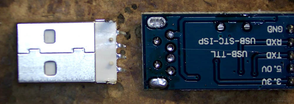
Removing the socket and the plug from their original places
I quickly removed the socket and the plug from their respective boards with hot air. I set the hot air to 450 °C with medium air flow, and tried to be as quick as possible to avoid damaging the sockets and the surrounding parts. Indeed, it took about 8 seconds each.
Assembly
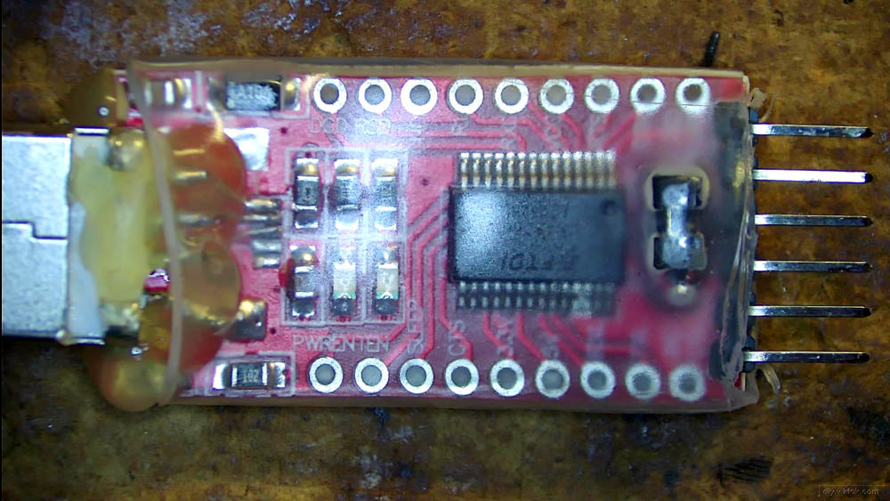
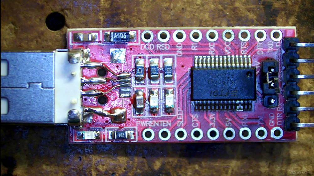
The USB Type-A plug and the Mini-B socket have exactly the opposite pinout. This is not coincidence – one is a plug (male), the other one is a socket (female). This means, I had to place the Type-A plug belly up on the PCB to align the pins with the old traces. To give some mechanical support to the plug, I soldered the jacket (shielding) of it to two of the solder pads of the old socket. Then using some pieces of 30 AWG copper wire I connected the plug’s pins to their respective traces on the PCB.
Then I did some testing: Double and triple checked the soldering job with a continuity meter, and when I didn’t find any problem, I plugged it in the USB hub. Windows immediately recognized the device and I even tried the serial communication with my project. Everything went smoothly, so I disconnected the little masterpiece carefully from the hub and cleaned it as much as I could:
Finishing touches
Once the PCB dried it was time to finish up this quick hack. I added a good dose of hot glue for additional mechanical support as well as covered the whole thing in a piece of heat-shrink tube: