Introduction
Almost a decade ago I made a PIC micro controlled staircase light timer. It has been working really well ever since and now time has come to upgrade it. This time I designed it around the ESP8266 WiFi module as most of my other projects these days. Having WiFi in the staircase timer allows it to be managed remotely and it also ties in nicely into my home automation system. Watch this space.

While getting a face lift, the device also got some cool new functions added which I will show below.
Design considerations
These are the requirements/goals for the new unit that I set up before starting the project:
- Just like its predecessor, it should be an install and forget type device. The previous unit worked almost 10 years without a hitch. I am hoping this new one will rise to the challenge!
- It should require no new cables installed in the staircase or anywhere else, i.e. it should be drop-in compatible with the previous unit.
- It should take, as an input, one of the many push buttons installed on every floor to start the staircase lights for a specified time interval after which it should switch them off.
- At or around sunset it should switch on the light right above the entrance so that people arriving home at night can find the keyhole easily. Also, at or around sunrise this entrance light should switch off. Until now the entrance light was switched on and off manually resulting in not having it on many times at night and forgotten on during the day. An automation should fix this.
- All the settings should be done remotely either through built-in web pages (like routers) and/or through MQTT so that it could become an integral part of my home automation system.
- It should work with no internet connection, it should depend on no third party service. As long as there is electricity it should work.
- The unit should be expandable in the future without having to start from scratch.
Hardware
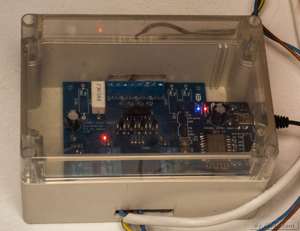
For this project I didn’t have to design a separate circuit. Instead, I borrowed two PCBs from other projects of mine: A control circuit with the core components and an I2C expansion board with 4 high voltage (mains) input and 4 relays capable of switching high voltage, low current (up to 10A). Repurposing existing designs meant a much faster development cycle as I didn’t have to order and wait for new PCBs.
Control board
The circuit can be powered by any decent smart phone charger through a USB-B mini socket. The ESP12-F module handles all the WiFi communication, has a built-in web server for remote administration and handles all the inputs and outputs via I2C on the daughter board using only 2 GPIOs.
Expansion board

The I2C expansion board uses a PCF8574 I2C expander chip so that the ESP12-F module can handle all the digital inputs and outputs needed using only 2 GPIO pins. I designed these boards sot that in the future they can be expanded with further similar boards if needed without having to redesign everything from scratch. Up to 8 of such boards can be connected to the controller board. These expansion boards can be simply daisy chained and only the firmware needs to be updated.
The high voltage inputs are electrically isolated by opto-couplers. I used a PC847 chip to save place as it contains 4 PC417 opto couplers in one package. The resistors limiting the current for the LEDs in the opto couplers are high wattage ones so that in the event of one of the push buttons breaks down in the staircase and remains a permanent short, they can dissipate the excess heat.
Parallel to the opto couplers I also fit a momentary push button for testing purposes.
Sponsorship
This project was sponsored by PCBWay. They do all kinds of PCB services at very reasonable prices. Why don’t you have your next PCB prototype done by them? You even get some discount by clicking here:

Firmware
I roll my own firmware on this device, which is available to anyone willing to try it out. The firmware is based on my ActoSenso platform, modified to suit the hardware setup of this device.
Some of its features are:
- Serial debugging
- Built-in web server for setting light parameters (like how long the staircase lights should be on after a button was pressed, how much before/after sunset/sunrise the external light should come turn on/off, etc)
- Uses MQTT which makes it compatible with any home automation system that uses MQTT.
- Can be controlled (its settings changed) via its web interface as well as via MQTT.
- Error and event logging through MQTT.
- OTA updates through wifi.
- Does not rely on Internet nor any third party services.
Sample pages from the web interface:


Conclusion
Using repurposed hardware modules from previous projects I managed to accomplish all design goals set out at the start. If new peripherals need to be sensed/controlled in the future, I only have to update the firmware and connect a few new cables to the unit.
Finally, a screenshot showing how it looks in my home automation system:


There is a hackaday that referenced your light bulb hack, that's how I found your stuff here. I have interest in esp for home use, I like what you are doing and your assessment of not trusting internet connections, cloud services and closed source apps. I'm just learning details of MQTT and things like echo, google home, etc. Are there open-source MQTT server apps that can be useful in local/non-internet use? Do you use it for home automation? I guess I was assuming MQTT was all about the cloud(echo, google home, etc), but maybe it's not. Can commodity things like echo or google home be used with these systems without annoying privacy issues/reliance/dependencies? What MQTT home automation systems would you use? Thanks for sharing your projects. kbongos.
I’m not sure what you mean by “MQTT server app”. If you are looking for an MQTT broker you can install and use, I can recommend Mosquitto, which I have been using for years now without a problem. Have a look at these article here:
http://diy.viktak.com/2015/05/installing-mosquitto-for-use-with.html
http://diy.viktak.com/2015/05/internet-of-things-iot-with-esp8266.html
Also, the project’s own web site: https://mosquitto.org/
Obviously, Amazon’s/Google’s/etc solutions are not going to work without internet connection, but I prefer it like that. I use Home Assistant for automation, and soon a whole new page will be added to my blog dedicated to just that.