This time I would like to walk through the “open source-ification” of another Tuya device. The reason for this is that this device requires a bit more effort and tools to program. The concept is the same:
- Open the case
- Create a backup
- Flash the new firmware
- Configure device
- Close case
The difficulty lies in the fact that this device has a different architecture. While in some other devices I covered before, the only logic chip is a BK7231N in some shape or way (i.e. a bare chip, a CB3S module, a CBU module, …), this device has another MCU (I couldn’t find any writing on the chip even under microscope). This chip is casually called the Tuya MCU (even though the BK7231 family of chips are also MCUs…) as the following diagram (taken from the Tuya web site) best describes it:
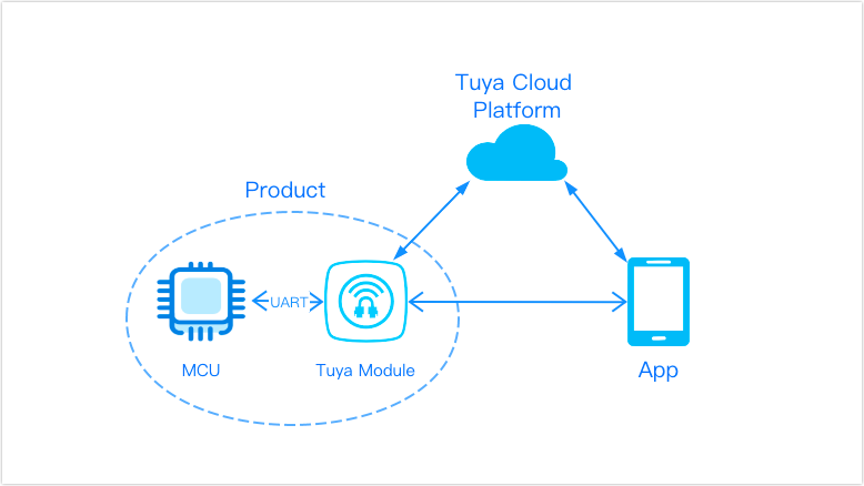
How a product like this works
In the above example, the Product is the whole PIR sensor. Its two major components are the MCU and the Tuya module:
The Tuya module only deals with the radio related tasks, i.e. sends and receives data to and from the Tuya Cloud, or in our case – after the firmware conversion, to our own MQTT server.
The MCU does the main function of the product, in our case it deals with the PIR sensor AND it talks to the Tuya module. This way the Tuya module only wakes up when a message needs to be sent to the “center”.
This architecture allows for significant savings in power needs, which is essential in a battery powered device. However, it also comes with a drawback (mostly for hackers): The two MCUs “talk” to each other using an UART. This means, that it is not possible to read or program the Tuya module (in this case the CB3S module) in-circuit. There are a number of ways to overcome this hurdle. We can temporarily
- remove the Tuya module from the PCB, program it, then solder it back.
- remove the MCU from the PCB so that we can read/program/configure the Tuya module, then solder it back.
- cut the MCU’s 2 pins to free the Rx and Tx lines so that we can read/program/configure the Tuya module, then solder them back.
- cut the Rx and Tx lines on the PCB so that we can read/program/configure the Tuya module, then fix them.
Probably there are a few more ways to accomplish the same thing, but these are the ones that come to mind first. I chose to remove the MCU from the PCB using hot air. The MCU is an 8 pin SOIC chip, easily handled even with a soldering iron.
Disassembly
This device is very easy to disassemble: The back plate, which doubles as a battery cover, simply slides off. After that there is a single screw holding the PCB in place. Here is how the PCB looks when removed from the white casing:
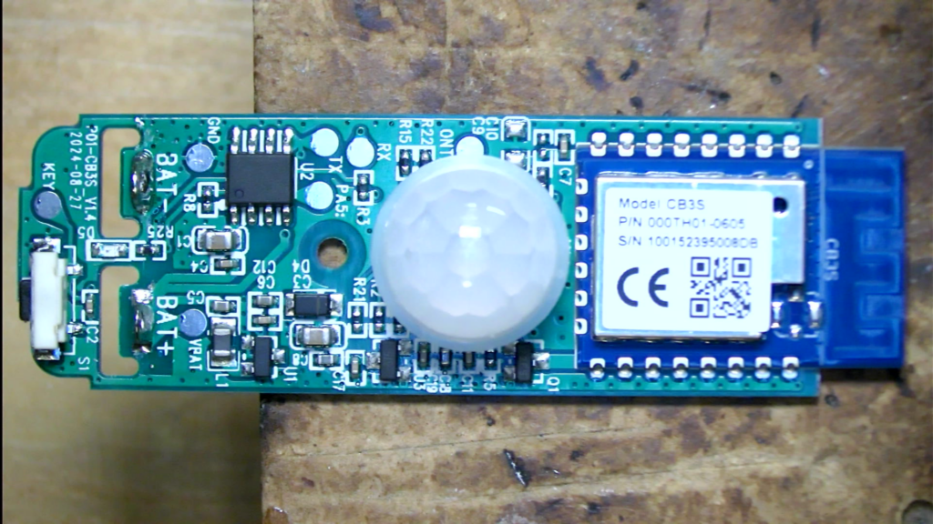
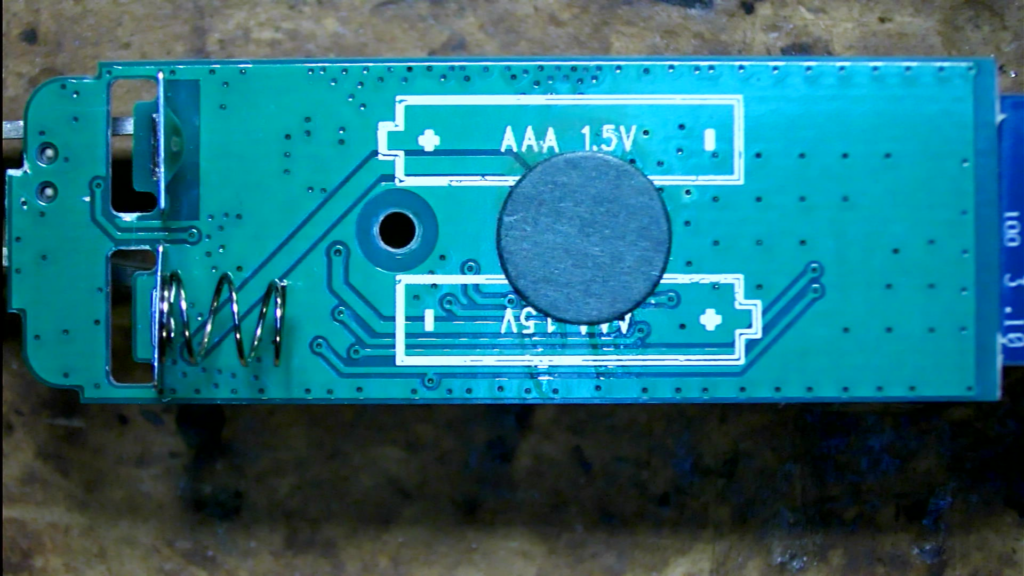
On the front you can recognize the radio module (CB3S) on the right, the large white dome of the PIR sensor in the center and the MCU in the top left corner(ish). On the back of the PCB you can see the battery terminals.
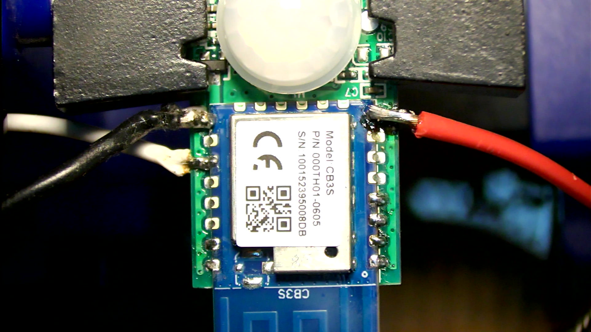
To prepare for the flashing process I removed the MCU and soldered some wires directly to the CB3S module:
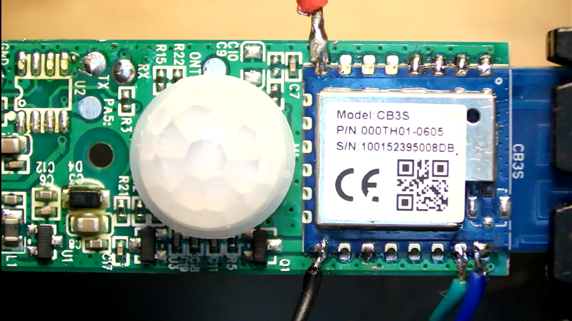
Red: 3.3V, Black: GND, Green: Rx, Blue: Tx. Soldering the 3.3V on the module is not really needed. When I did it like this, I did not know yet that the MCU controlled power to the CB3S module by cutting the GND line rather than the Vcc line. If you are interested in seeing some debug messages coming from the CB3S module you can also connect a wire to the 3rd pin from the left in the bottom row (Tx of another UART on the CB3S module).
Once this is done, the flashing process is straightforward. It is the same as with any other similar device. Just connect GND, 3.3V, Rx and Tx to the appropriate pins of the (3.3V!!!) USB-UART adapter and you’re on your way. I recommend taking a backup of the factory firmware first, just in case. You can see how I did that in my previous article.
Configuration
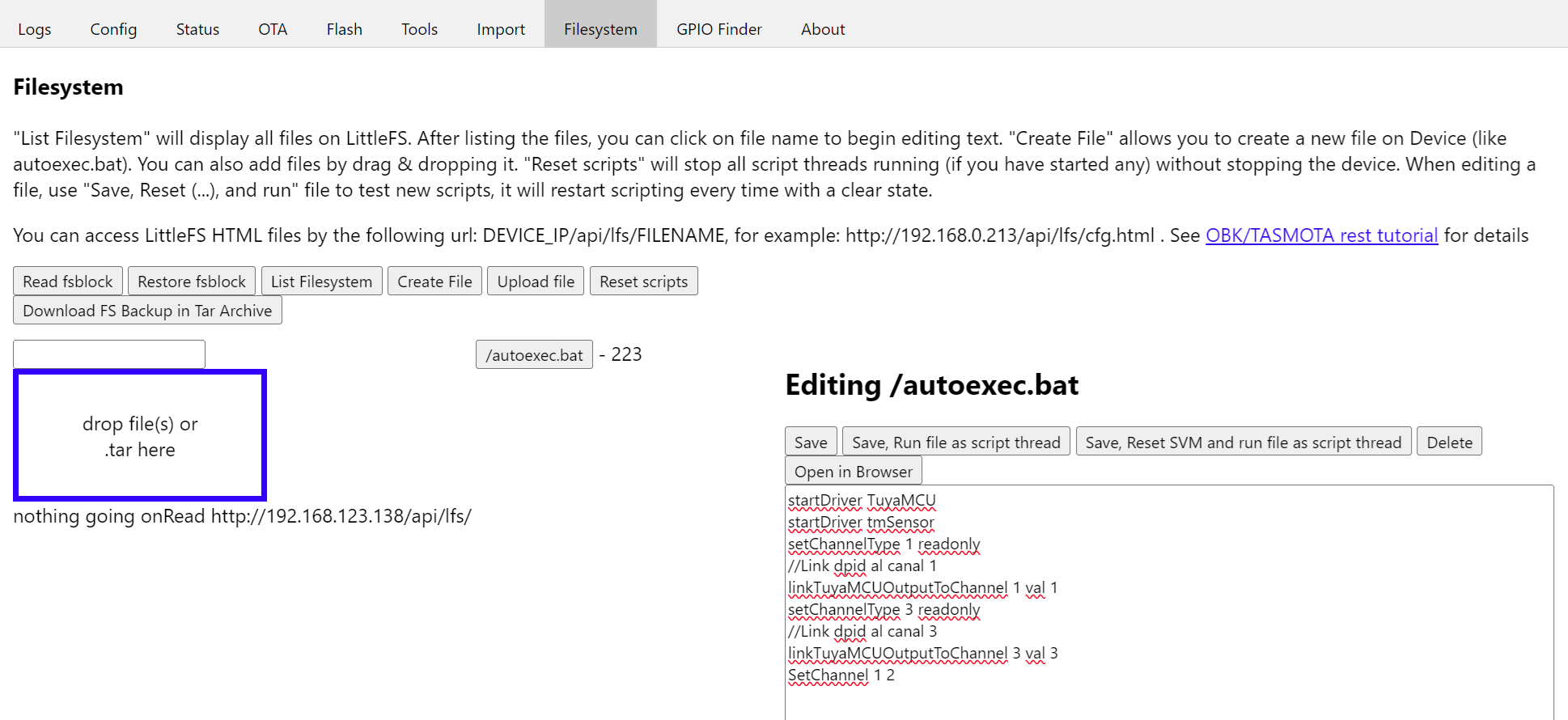
Once the new firmware is successfully flashed, some configuration needs to be done. This is necessary before you can revert the device to its original shape. These are the most important settings: Obviously, the wifi settings need to be correct, otherwise it won’t be able to connect to your network. You should also configure the MQTT settings so that the device can notify you. Finally, you have to launch the web app of the device and create an Autoexec.bat file with the following content:
startDriver TuyaMCU
startDriver tmSensor
setChannelType 1 readonly
//Link dpid al canal 1
linkTuyaMCUOutputToChannel 1 val 1
setChannelType 3 readonly
//Link dpid al canal 3
linkTuyaMCUOutputToChannel 3 val 3
SetChannel 1 2
It should look something like this:
After restart the device works as expected:
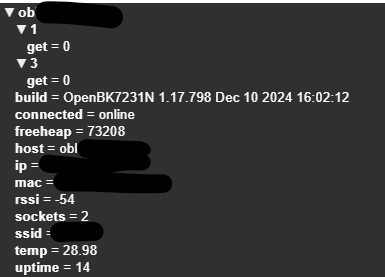
The temporary wires can now be removed, the PCB can be mounted back in its housing and the device is now ready for normal use.

I tend to swap out the beken chip with ESP12
What was the battery life like after doing this ?
It’s been a bit over a month now, haven’t changed the batteries yet. It is still to be seen.
Hi, I’ve flashed the device and have access to the web application, but I don’t understand how to set it up and use it further.
Well, it depends on your environment, i.e. if you use it with some home automation system, like Home Assistant, etc.
Generally speaking:
1. Connect o the the device’s IP address, i.e. 192.168.0.4
2. Click on Launch Web Application
3. Click Import
4. Paste the device’s configuration
5. Submit/Reboot
6. Configure other settings by opening the device’s configuration page again.