In this article I show how to convert a Tuya WiFi-IR Remote to use open source software. The reasoning and the procedure is the same or very similar to what I described in my previous article. (If you want more WiFi-IR gateway goodness, here is one I made a couple of years ago.)
Here are the steps needed for the conversion that I will cover:
- Remove the casing to get access to the PCB and the microcontroller
- Attach (solder) cables to the microcontroller
- Connect the other end of the wires to the serial port on the PC
- Confirm the unit is working by looking at the bootlog
- Change the wires for the programming port
- Backup the original firmware
- Flash the new firmware
- Configure the device
- Remove the wires used for programming
- Re-build the casing
And here are the tools needed:
- PC or laptop with a spare USB port
- USB-UART adapter
- 3 pieces of (thin) wires
- Soldering iron and some solder
- Serial terminal (Putty or similar) to verify the functioning of the device
- BK7231 GUI Flash Tool – download it here
In this article I will only show the procedure with as many pictures as necessary for anyone to follow.
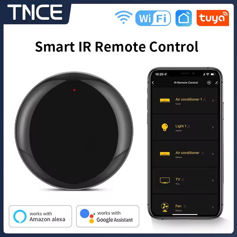
1. Opening the case
With a thin but strong prying tool gently detach the two parts of the shell. The line where they are connected can easily be seen. The two halves are held together by 3 flaps – be careful to not break them off. If you break them, don’t worry. You can use some hot glue to put the thing together at the end. No panic.
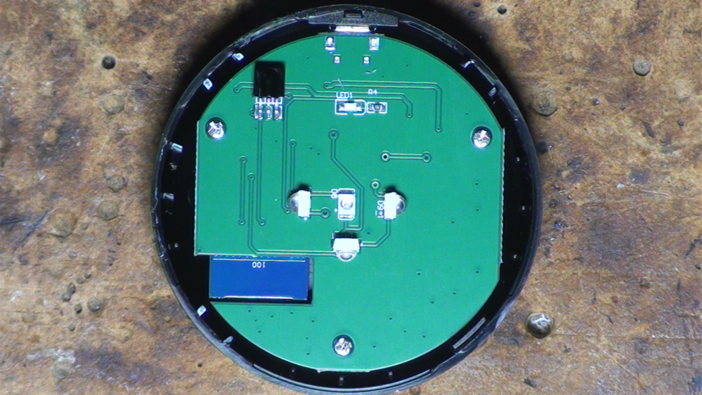
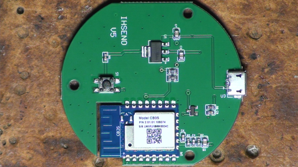
2-3. Attach wires to some of the MCUs pins
To program the MCU we need three wires: GND, Tx and Rx. The CB3S module uses a BK7231N chip. This uses 2 UARTS: one for monitoring the chip, one for programming it. We don’t need both at the same time. So let’s connect the GND, Tx according to the image below:
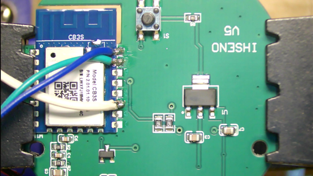
Tx, green-Rx – Monitoring: white-TxNote that I did not solder any wire for GND. This is because my 5V supply shares the GND with my PC. If you have a different setup, you also need to connect a wire to the GND pin. It is located 2 pins down from the white wire in the bottom right corner of the MCU.
Connect the other end of the wires to the serial-UART adapter on your PC. Make sure that any Rx pin is connected to a Tx pin at the other end and vice versa.
4. Confirm the unit is working by looking at the bootlog
Start a serial terminal application (i.e. Putty) on your PC. Set it to the serial port you connected your device to, set its speed to 115200 bps, leave the rest of the settings at their defaults, then plug in the USB cable into the device to power it up. If everything is wired up correctly, you should get an output similar to this:
V:BK7231N_1.0.1
REG:cpsr     spsr     r13      r14
SVC:000000D3          00401C1C 000033AC
IRQ:000000d2 00000010 00401e0c c18f2460
FIR:000000d1 00000010 00401ffc 7660b080
SYS:000000df          0040192c 00000158
ST:00000000
J 0x10000
bk_misc_init_start_type 0 0
prvHeapInit-start addr:0x411550, size:125616
[Flash]id:0xeb6015
sctrl_sta_ps_init
cset:0 0 0 0
[01-01 18:12:15 TUYA Info][lr:0xae5d5] mqc app init ...
[01-01 18:12:15 TUYA Info][lr:0xa6b6f] thread_create name:sys_timer,stackDepth:4096,totalstackDepth:4096,priority:5
[01-01 18:12:15 TUYA Info][lr:0xa6b6f] thread_create name:cmmod,stackDepth:4096,totalstackDepth:8192,priority:4
[01-01 18:12:15 TUYA Debug][lr:0xae583] mq_pro:5 cnt:1
[01-01 18:12:15 TUYA Debug][lr:0xae583] mq_pro:31 cnt:2
[01-01 18:12:15 TUYA Debug][lr:0xa69fb] Thread:sys_timer Exec Start. Set to Running Stat
[01-01 18:12:15 TUYA Err][lr:0xa5627] logseq empty
[01-01 18:12:15 TUYA Debug][lr:0x9e08f] svc online log init success
[01-01 18:12:15 TUYA Info][lr:0xa6b6f] thread_create name:wk_th-0,stackDepth:5120,totalstackDepth:13312,priority:3
[01-01 18:12:15 TUYA Err][lr:0xacdf9] wd_protected_read fails gw_bi -1
[01-01 18:12:15 TUYA Debug][lr:0xad0bb] gw base read finish:-1
[01-01 18:12:15 TUYA Debug][lr:0x9950d] ty bt cmmod regist ok:1
[01-01 18:12:15 TUYA Debug][lr:0x99925] upd adv para, send conn_req beacon.
[PLATFORM DEBUG]!!!!!!!!!!tuya_os_adapt_bt_port_init
[01-01 18:1ble mac:38-2c-e5-f3-8b-2:15 TUYA Notice][lr:0x39
xvr_reg_init
h4tl_99d2b] ble sdk re_initeinit-1 ok
dci_init ok
[01-01 18:12:15 TUYA
                    !!!!!!init_type=0
                                     rwble Notice][lr:0x995f7] ty_hl_init ok
rwble_init bt sdk init finish
 ok
[01-01 18:12:15 TUYA De
                       [ble_appm_send_gapm_rebug][lr:0x59d1b] < TUYAset_cmd]
 IOT SDK V:2.3.1 BS:40.0
                        enter normal mode
!!!!!!init_type=1
                 llm_init:312
0_PT:2.2_LAN:3.3_[gapm_cmp_evt_handler] CAD:1.0.3_CD:1.0.0 >
<conidx:0,operation:0x1, BUILD AT:2021_09_14_13status:0x0
cmd->addr.a_24_21 BY embed FOR ty_iddr[5] :0
!!!!!!init_tot_sdk AT bk7231n >
IOype=2
       [gapm_cmp_evt_hanT DEFS < WIFI_GW:1 DEBUdler] conidx:0,operatioG:1 KV_FILE:0 SHUTDOWN_n:0x3,status:0x0
gapm_MODE:0 LITTLE_END:1 TLScmp_evt:GAPM_SET_DEV_CON_MODE:2 ENABLE_LOCAL_LIFIG
gapm_cmp_evt:wait NKAGE:0 ENABLE_CLOUD_OPGAPM_GEN_RAND_NB
ERATI[gapm_cmp_evt_handler] ON:0 ENABLE_SUBDEVICE:0conidx:0,operation:0x1a ENABLE_ENGINEER_TO_NOR,status:0x0
gapm_cmp_evMAL:0 OPERATING_SYSTEM:t:GAPM_GEN_RAND_NB
2 E[gapm_cmp_evt_handler] NABLE_SYS_RPC:0 TY_SECUconidx:0,operation:0x1aRITY_CHIP:0 RELIABLE_TR,status:0x0
gapm_cmp_eANSFER:RELIABLE_TRANSFEvt:GAPM_GEN_RAND_NB
[gaR ENABLE_LAN_ENCRYPTIONpm_cmp_evt_handler] con:1 ENABLE_LAN_LINKAGE:0idx:0,operation:0x28,st ENABLE_LAN_LINKAGE_MASatus:0x0
gapm_cmp_evt:TER:0 ENABLE_LAN_DEV:0 BLE_STACK_OK
[PLATFORM ENABLE_LAN_DEV_MASTER:0NOTICE]STACK INIT OK
b >

[01-01 18:12:15 Tle create new db
ble_eUYA Debug][lr:0x59d25] nv->start_hdl = 0x10
[oem_bk7231n_irbox_mol_tPLATFORM NOTICE]CREATE y:2.0.0
DB SUCCESS
[PLATFORM DEBUG]!!!!!!!!!!tuya_os_adapt_bt_reset_adv
[01-01 18:12:15 TUYA Notice][lr:0x99a3d] ble adv upd!
[PLATFORM NOTICE]!!!!!!!!!!tuya_before_netcfg_cb
[appm[01-01 18:12:15 TUYA No_create_advertising]
[btice][lr:0xb993f] key_ale_appm_create_advertisddr: 0x1ee000   block_sing]
adv_state:1
[gapz 4096
m_cmp_evt_handler] conidx:0,operation:0x1b,status:0x0
adv_actv_idx:0,tx_pwr:0
[PLATFORM DEBUG]UNKNOW EVENT:17
[gapm_cmp_evt_hand[01-01 18:12:15 TUYA Noler] conidx:0,operationtice][lr:0xb9a0f] get k:0xa0,status:0x0
[appmey:
0xde 0x4 0xbf 0x80_adv_fsm_next] cur adv_s 0xb7 0x8b 0xd6 0x69 0xtate:1
adv_state:2
[b5 0x77 0xaf 0x29 0xa2 0le_appm_set_adv_data]sex8a 0x7b 0x21
t data:02:01:06:03:02:01:a2:04:16:01:a2:00:00:00:00:00:00:00:00:00:00:00:00:00:00:00:00:00
[appm_set_adv_data]ret:0
end adv_state:2
[PLATFORM DEBUG]UNKNOW EVENT:16
[gapm_cmp_evt_handler] conidx:0,operation:0xa9,status:0x0
[appm_adv_fsm_next] cur adv_state:2
[appm_set_scan_rsp_data]
adv_state:3
[ble_appm_set_scan_rsp_data]
end adv_state:3
[PLATFORM DEBUG]UNKNOW EVENT:16
[gapm_cmp_evt_handler] conidx:0,operation:0xaa,status:0x0
[appm_adv_fsm_next] cur adv_state:3
[appm_start_advertising_cmd]
adv_state:6
[ble_appm_start_advertising]
end adv_state:6
[PLATFORM DEBUG]UNKNOW EVENT:16
[gapm_cmp_evt_handler] conidx:0,operation:0xa4,status:0x0
[appm_adv_fsm_next] cur adv_state:6
adv_state:7
end adv_state:7
[PLATFORM DEBUG]UNKNOW EVENT:16
[01-01 18:12:15 TUYA Info][lr:0xa6b6f] thread_create name:mf_test,stackDepth:5120,totalstackDepth:18432,priority:4
bandgap_calm_in_efuse=0x72
[load]bandgap_calm=0x72->0x32,vddig=4->5
[FUNC]rwnxl_init
[bk]tx_txdesc_flush
[FUNC]intc_init
[FUNC]calibration_main
gpio_level=1,txpwr_state=15
                           user define rfcali mode:1
get rfcali_mode:1
DPLL Unlock
DPLL Unlock
calibration_main over
                     flash txpwr table:0xf
dif g and n20 ID in flash:4
dif g and n40 ID in flash:4
read txpwr tab from flash success
temp in flash is:325
xtal in flash is:78
xtal_cali:78
--init_xtal = 78
                [FUNC]ps_init
[FUNC]func_init_extended OVER!!!

start_type:0
Version:
Initializing TCP/IP stack
tcp_port:62642
app_init finished
[01-01 18:12:15 TUYA Notice][lr:0x58cc9] mf_init succ
[01-01 18:12:15 TUYA Notice][lr:0x595b5] pConfig = {reset_pin:6,wfst_pin:8,owm:1,reset_lv:0,rsthold:3,wfst_lv:1,netyc:1,infrr:7,netnc:0,infre:26,crc:42,}---config len:102
[01-01 18:12:16 TUYA Notice][lr:0x59709] key:reset_pin:-----val:6----len:1
[01-01 18:12:16 TUYA Notice][lr:0x59709] key:reset_lv:-----val:0----len:1
[01-01 18:12:16 TUYA Notice][lr:0x59709] key:infre:-----val:26----len:1
[01-01 18:12:16 TUYA Notice][lr:0x59709] key:infrr:-----val:7----len:1
[01-01 18:12:16 TUYA Notice][lr:0x59709] key:wfst_pin:-----val:8----len:1
[01-01 18:12:16 TUYA Notice][lr:0x59709] key:wfst_lv:-----val:1----len:1
[01-01 18:12:16 TUYA Notice][lr:0x59709] key:rsthold:-----val:3----len:1
[01-01 18:12:16 TUYA Notice][lr:0x59709] key:owm:-----val:1----len:1
[01-01 18:12:16 TUYA Notice][lr:0x59709] key:netyc:-----val:1----len:1
[01-01 18:12:16 TUYA Notice][lr:0x59709] key:netnc:-----val:0----len:1
[01-01 18:12:16 TUYA Notice][lr:0x594c7] ir_send =26
[01-01 18:12:16 TUYA Notice][lr:0x594cf] ir_recv =7
[01-01 18:12:16 TUYA Notice][lr:0x594d7] owm =1
[01-01 18:12:16 TUYA Notice][lr:0x594df] led detect_sta =1
[01-01 18:12:16 TUYA Notice][lr:0x594e7] led_num =8
[01-01 18:12:16 TUYA Notice][lr:0x594ef] netn =0
[01-01 18:12:16 TUYA Notice][lr:0x594f7] nety =1
[01-01 18:12:16 TUYA Notice][lr:0x594ff] key detect_sta =0
[01-01 18:12:16 TUYA Notice][lr:0x59507] key_num =6
[01-01 18:12:16 TUYA Notice][lr:0x5950f] long_key_time =3
[01-01 18:12:16 TUYA Notice][lr:0x58d31] current product ssid name:tuya_mdev_test1
[sa_sta]MM_RESET_REQ
[bk]tx_txdesc_flush
[sa_sta]ME_CONFIG_REQ
[sa_sta]ME_CHAN_CONFIG_REQ
[sa_sta]MM_START_REQ
ht in scan
scan_start_req_handler
temperature_type=2
                  temp_code:20 - adc_code:335 - adc_trend:[13]:325->[12]:335
[PLATFORM NOTICE]bk_rst:0 tuya_rst:0
[01-01 18:12:18 TUYA Notice][lr:0xac27b] Last reset reason: 0
[01-01 18:12:18 TUYA Info][lr:0xa6b6f] thread_create name:health_monitor,stackDepth:1536,totalstackDepth:19968,priority:5
[01-01 18:12:18 TUYA Notice][lr:0xac3eb] serial_no:382ce5f38b38
rw_ieee80211_set_country code:
code: CN
channel: 1 - 13
mode: MANUAL
bk_wlan cca closed
[01-01 18:12:18 TUYA Notice][lr:0xac423] gw_cntl.gw_wsm.stat:0
[01-01 18:12:18 TUYA Err][lr:0xac451] read wf start mode err:-6
[01-01 18:12:18 TUYA Notice][lr:0xac4b1] gw_cntl.gw_wsm.nc_tp:1
[01-01 18:12:18 TUYA Notice][lr:0xac4b9] gw_cntl.gw_wsm.md:0
[01-01 18:12:18 TUYA Notice][lr:0xac6a7] gw_cntl.gw_if.abi:0 input:0
[01-01 18:12:18 TUYA Notice][lr:0xac6b3] gw_cntl.gw_if.product_key:key54vrth5askhsj, input:key54vrth5askhsj
[01-01 18:12:18 TUYA Notice][lr:0xac6bf] gw_cntl.gw_if.tp:0, input:0
[01-01 18:12:18 TUYA Notice][lr:0xac6cf] gw_cntl.gw_if.firmware_key:key54vrth5askhsj, input:key54vrth5askhsj
[01-01 18:12:18 TUYA Notice][lr:0x9964b] ty bt upd product:key54vrth5askhsj 1
[01-01 18:12:18 TUYA Notice][lr:0x99bc3] upd product_id type:1 key54vrth5askhsj a59dee73f7585b2a 6pTAffjKhZVnwqbSEO5aTV6vv8maHgxT
[01-01 18:12:18 TUYA Info][lr:0xa6b6f] thread_create name:key_handle,stackDepth:2048,totalstackDepth:22016,priority:5
bk pwm initial:mode = 29
bk pwm initial:duty_cycle1 = 156
[01-01 18:12:18 TUYA Info][lr:0xa6b6f] thread_create name:irapp_thrd,stackDepth:2048,totalstackDepth:24064,priority:3
[01-01 18:12:18 TUYA Info][lr:0xa6b6f] thread_create name:irapp_studysync_thrd,stackDepth:1024,totalstackDepth:25088,priority:3
[01-01 18:12:18 TUYA Notice][lr:0x59e19] device_init ok  free_mem_size:64408
[sa_sta]MM_RESET_REQ
[bk]tx_txdesc_flush
[sa_sta]ME_CONFIG_REQ
[sa_sta]ME_CHAN_CONFIG_REQ
[sa_sta]MM_START_REQ
ht in scan
scan_start_req_handler
[01-01 18:12:18 TUYA Notice][lr:0x580bd] remain size:63584
net_wlan_add_netif not vif idx found
supplicant_main_exiting
supplicant_exit_done
hostapd_main_exiting
hostapd_exit_handler
hostapd_exit_done
net_wlan_add_netif not vif idx found
supplicant_main_exiting
supplicant_exit_done
Soft_AP_start
[saap]MM_RESET_REQ
[bk]tx_txdesc_flush
[saap]ME_CONFIG_REQ
[saap]ME_CHAN_CONFIG_REQ
[saap]MM_START_REQ
apm start with vif:0
me_set_ps_disable:840 0 0 1 0 0
------beacon_int_set:100 TU
set_active param 0
                  [msg]APM_STOP_CFM
                                   update_ongoing_1_bcn_update
hal_machw_enter_monitor_mode
[01-01 18:12:21 TUYA Notice][lr:0x99c47] update bound stat:0
[PLATFORM DEBUG]!!!!!!!!!!tuya_os_adapt_bt_reset_adv
adv_state:12
!!!!!!!!!!ble_appm_update_adv_data updata adv data
[gapm_cmp_evt_handler] conidx:0,operation:0xa9,status:0x0
[appm_adv_fsm_next] cur adv_state:c
adv_state:13
[ble_appm_set_scan_rsp_data]
end adv_state:d
[PLATFORM DEBUG]UNKNOW EVENT:19
[PLATFORM DEBUG]UNKNOW EVENT:16
[gapm_cmp_evt_handler] conidx:0,operation:0xaa,status:0x0
[appm_adv_fsm_next] cur adv_state:d
adv_state:7
end adv_state:7
[PLATFORM DEBUG]UNKNOW EVENT:20
[PLATFORM DEBUG]UNKNOW EVENT:16
[01-01 18:12:21 TUYA Notice][lr:0x99a3d] ble adv upd!
[01-01 18:12:21 TUYA Notice][lr:0x59c8d] wifi_stat:1
temp_code:25 - adc_code:326 - adc_trend:[12]:335->[13]:325
If you get something similar, you can move onto the next step. If you get garbage characters, check your communication settings in the terminal program. They should be like this: 115200kbs, 8N1. If you don’t see any output, check your wiring.
5. Change the wires for the programming port
To prepare for the actual programming of the MCU we need to use the other UART on the chip. You need to use the blue and green wires. Again, make sure that any Rx pin is connected to a Tx pin at the other end and vice versa.
6. Backup the original firmware
Fire up the BK7231 GUI Flash Tool and set it up like this:
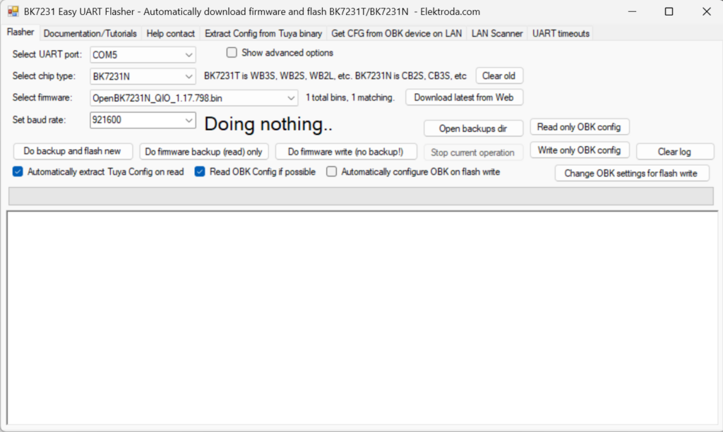
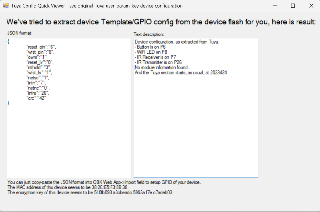
Finally click on Do firmware backup (read) only to create a backup of the original firmware. Once the connection is established with the MCU you will be prompted to power cycle the MCU. This is easily done by removing the USB power cable for a moment, then reconnecting it. Reading the content of the MCU will automatically start. This process should take a few seconds only. At the end you will be presented, in a new window, the configuration of the old firmware. We can use this later to configure the new firmware, so save it somewhere safe. My configuration was something like this:
7. Flash the new firmware
It is now time to flash the new firmware. The process is similar to the previous step with the difference that you need to click on “Do firmware write (no backup!)” to initiate the process. Once the flashing is done, a happy, green message is shown:
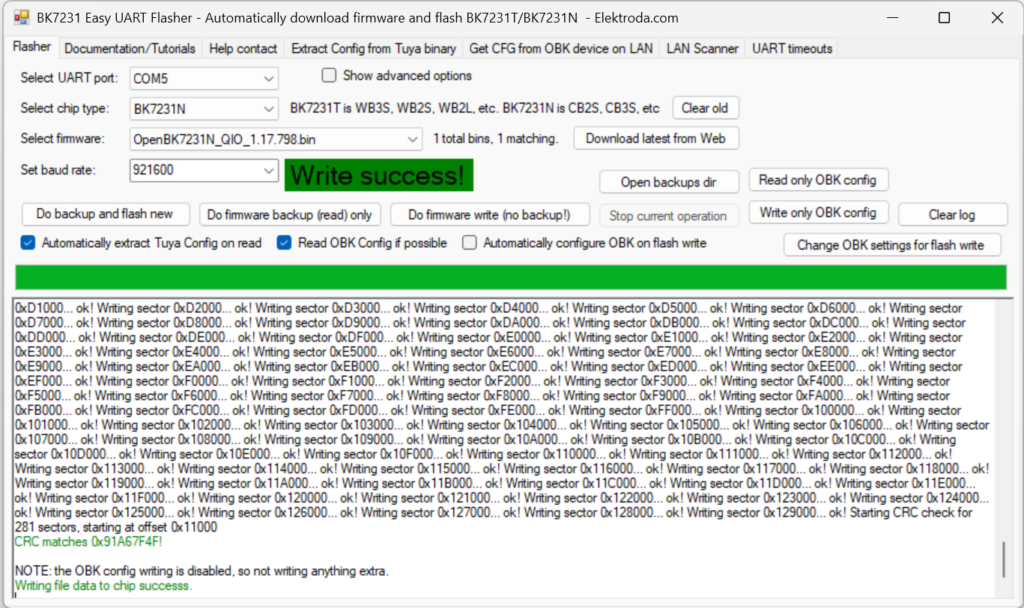
At this stage the device is ready to be configured.
8. Configure the device
First, power cycle the device. As it will have no knowledge of your WiFi network, it will enter Access Point mode. So use a mobile device, i.e. your phone, to connect to it (the SSID will be something like OpenBK7231N_XXXXXXXX). No password is required. Navigate to 192.168.4.1, then click Configure then Configure WiFi & Web, fill out the form, then click Submit to save the settings. After restarting, the device will connect your WiFi network and you can configure it further.
To configure the device there are several options. The easiest is to use the Web Application:
Navigate to the IP address of the freshly flashed device (get the address from your router), click Launch Web Application, finally click Import. Under Enter template here copy and paste this template:
|
1 2 3 4 5 6 7 8 9 10 11 12 13 14 15 16 17 18 19 20 21 22 23 |
{ "vendor": "Tuya", "bDetailed": "0", "name": "Full Device Name Here", "model": "enter short model name here", "chip": "BK7231N", "board": "TODO", "flags": "4244480", "keywords": [ "TODO", "TODO", "TODO" ], "pins": { "6": "Btn;0", "7": "IRRecv;2", "8": "WifiLED;1", "26": "IRSend;3" }, "command": "", "image": "https://obrazki.elektroda.pl/YOUR_IMAGE.jpg", "wiki": "https://www.elektroda.com/rtvforum/topic_YOUR_TOPIC.html" } |
Then click Clear OBK and apply new script from above to apply the changes.
Now go to the Filesystem tab of the web application and create a new file called autoexec.bat. Once created, click on it to edit it. Copy and paste the following into it:
startDriver IRThis line is needed to start the IR module in the MCU every time it boots.
Finally click Save, then restart the device.
You can also several other aspects of the device, which is outside the scope of this article.
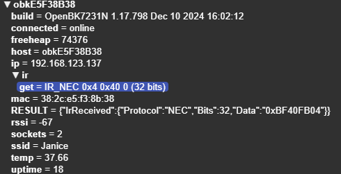
Here is a screenshot of some sample MQTT messages spat out by the device when “attacked” by a remote control:
9-10. Finishing up
Remove the temporary wires and reassemble the case to rep up the conversion.
Congratulations, you now have a fully working, privacy respecting WiFi-IR remote!


Thanks for this! I just happened to purchase the same device and was wondering what were the pins used.