Introduction
Although my “original” Spindicator itself was just a clone of this one, mine was well received by the geeks around the world! 🙂 A fellow diy tinkerer made an even better one with PWM control (very cool, indeed!).
Recently, I was asked to do something similar for a custom XBOX 360 enclosure project. So I got back to the drawing board and came up with a design that would have the following features:
- works from the 5V DC provided by the motherboard
- the running light should leave a trail
- has 4 green LEDs (like the Guide button on the XBOX 360 controller)
- small form factor (not greater than 2″ x 2″)
This is a short demo of the finished circuit currently sitting in one of my test PCs:
Hardware/Operation
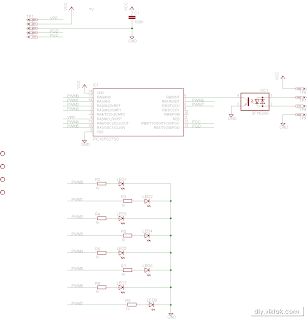
The full schematics:
 |
| Very few components are used to make this Spindicator clone. |
My new design is based around Microchip’s PIC16F648A microcontroller. I have used this PIC micro in a few projects in the past so by now I am fairly comfortable with it. It only has one hardware PWM module, so driving 4 or more LEDs can only be done in software.
An 817 opto-coupler still takes the pulses from the motherboard. I used a TTH version of this opto coupler, because I have plenty of them on stock. On the PCB though, I have designed the SMD version to save space. It is easy to use the TTH version in the SMD spot: I just cut the pins to size – works perfectly.
The output of the opto-coupler goes directly to the microcontroller’s external interrupt input: every time a pulse is detected an interrupt occurs. This is how the microcontroller “knows” how fast the activity LED is supposed to be flashing.
After the PWM magic in the firmware there’s not much to explain: each output has an LED and a current limiting resistor. The resistors are chosen such that the LED current is less than 15mA at 100% PWM duty cycle. Because of the trailing effect this time each LED must have its own current limiting resistor.
 |
| Front side of the bare PCB. Note: R1 is not used and is already removed from the schematics. |
 |
| Back side of the PCB. Final measurements: 36mm x 36mm (1.4″ x 1.4″) |
In the current design of the firmware, up to 11 LEDs can be connected to the microcontroller:
11 LEDs are used on at this stage on the breadboard.
In the hardware design I made room for only 8. On the test board I made it first with 11 LEDs but it just didn’t seem right. For the original request (for the XBOX 360) I only use 4 LEDs, every other LEDs are simply not soldered in place.
The final circuit (actually 2 of them) for the XBOX 360.
Note: The LEDs are not yet soldered in place – they will be finalized when mounting them on the custom XBOX 360 enclosure.
Note: The LEDs are not yet soldered in place – they will be finalized when mounting them on the custom XBOX 360 enclosure.
In the hardware design I made room for only 8. On the test board I made it first with 11 LEDs but it just didn’t seem right. For the original request (for the XBOX 360) I only use 4 LEDs, every other LEDs are simply not soldered in place.
Firmware
The firmware is very simple, and for easy customization I included compiler options to build versions for 4 and 8 LED versions.
The firmware was written in XC8 v1.12. It is available on request.
Summary
I have accomplished all the goals (features) I was set at the beginning of the project. Once I was done with all this I added an extra feature: when the disk activity is so high that the “running” LED catches up with its trail, then the intensity of the leading LED gets higher resulting in a pulsing ring effect, like the power LED on some laptops.
I think I have had enough of spindicators for a while now, but I can’t promise I won’t come up with something new in the future 🙂
Finally, another video of it:
This project is licensed under a Creative Commons Attribution-NonCommercial-ShareAlike 3.0 Unported License.
Finally, another video of it:
Licensing

This project is licensed under a Creative Commons Attribution-NonCommercial-ShareAlike 3.0 Unported License.

