Introduction
The geek inside me has always wanted a fridge that shows the inside temperature for both the freezer and the fridge compartments. However, when we recently replaced our very old fridge we ended up getting a new one without the built in thermometer. So I decided that one of my next projects would have to rectify this problem.
 |
| This dual thermometer can also be used to measure inside and outside temperatures at home. |
Hardware
Since all I wanted was to show two different temperatures, the circuit is very simple. It contains the temperature sensors, the display modules and a microcontroller to manage some simple tasks.
The microcontroller of choice was a PIC16F886 because I had used it for some experiments and wanted to build it into something. It has all the functions I needed, e.g. an internal oscillator to cut down on external parts needed, a timer for refreshing the display, enough digital I/O lines for connecting to two display modules without extra hardware.
The display modules are some common cathode 4 digit 7 segment ones. The advantage of these common cathode (or anode) modules is that they use less microcontroller I/O lines then ordinary 7 segment modules. The drawback is that the software is a little more complex since the displayed values must constantly be refreshed. At any given time there is only one digit displayed, all the others are off. Displaying 8 digits for 1ms each means that refreshing rate is about 8ms, or 125Hz. This is fast enough for the human eye to not see separate digits flashing but a constant set of characters.
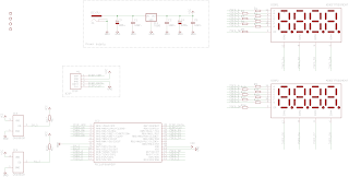 |
| Schematics of the dual thermometer |
The temperature sensing part I used for this project is a high-precision 1-Wire digital thermometer chip from Dallas Semiconductors. There are a number of similar ones available; I used the DS1820 because I have a few of them left over from previous projects. This one uses the 1-Wire protocol to communicate with the PIC, doesn’t need any external components and it’s easy to be placed inside a fridge.
The 1-Wire protocol allows many 1-Wire devices to use the same data line but the software overhead is so high (at least in assembly) that I decided to use two separate lines for the two thermometers. This is not the most elegant thing to do but I didn’t find any assembly code on the internet I could stealborrow. Having two 1-Wire lines made my code a lot longer than it could be but this time I had plenty of program memory in the PIC. This chip provides the results of the measurements in Celsius format.
Of course, a mandatory ICSP header is also included on the board, just in case.
I tend to use as many SMD parts as I can to save on PCB size and make it look nicer. This time, however, the PIC I used is a TTH version because I had that already and wanted to use it up.
Operation
After connecting the circuit to power (>7.5VDC, a 7805 regulator is on board) first it does a display test for a few seconds then it starts normal operation. Temperature is measured about once per second.
At the moment the resolution of the temperature displayed is 0.5C. This can be further refined from software. I might do it in the future, but for now I am eager to get it in the fridge and the living room.
Enclosure
This time I decided to put the PCB behind a modified transparent photograph holder which I got for about half a euro in the local stationery store: First I cut off the rear part of the plexiglass (that normally would hold the photograph against the front one), then I drilled 4 holes into the front one and with the help of some long screws I mounted the circuit behind it.
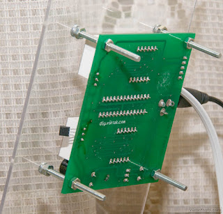 |
| Here you can see easily how I mounted the PCB on the back of the clear plexiglass. |


Nice project !
Do you plan to publish the software source code?
Greetings from Germany
Eric
@Anonymous: I'm afraid I won't put the code on the site but if you send me a private mail I will send it to you.
I would like to see the code to, i have a project with I-button and a PIC32 going on.
Nice projekt btw, From Denmark
@Anonymous: I'm afraid I won't put the code on the site but if you send me a private mail I will send it to you.
Vitya, how is DS1820 and the wiring holding up in the fridge so far? I mean, it's a pretty humid place, how did you seal it? I'm thinking of building a similar device where I would need to see the temperature difference between the inside the house and outside (an experiment having to do with the house insulation). How far from the PIC the DS1820 can be located, do you know?
And I also need to ask about the code: will you make it available at some point in the future? I will definitely need to make changes because I would need it to show not only the two temperatures but also the difference between them (so I don't have to carry a calculator around).
Keep up great work!
Cheers!
@ElectroNick: They look OK so far. I sealed only the pins of the DS1820 with hot glue. I forgot to mention this in the article. Also, as it turns out, you have to be careful with it – if you fiddle around with the hot glue too much, the chip overheats and looses its calibration (which I don't know how to fix, if it is possible at all). I found this out the hard way – now I have a DS1820 which about 60 degrees off… 🙁
@ElectroNick: The cable I am using is about 2 meters – I don't know the limit, but it's much longer than if I used a sensor with analog output.
Please send me the code or .hex file for this project on my email, kontakt@cr.mk
Thanks
Code sent in private mail.
Can you send the source code n hex file for this project to my email: yeeboon1115@hotmail.com. Thanks.
Code sent in private mail.
Nice project! What is the temperature range?
According to the manufacturer:
Measures Temperatures from -55°C to +125°C (-67°F to +257°F)
±0.5°C Accuracy from -10°C to +85°C
Source: http://www.maxim-ic.com/datasheet/index.mvp/id/2812
It looks very well. I see some ports are free. You can put a little buzzer to have an alarm when door fridge is opened too long. I see somewhere on net an ideea to put an photoresistor an measure the time of how long the light is on.
Please send me the code for this project on, valibb@gmail.com
Thank you
Yes, there are some IOs left for custom use. I didn't use them because I don't need anything else – my fridge already beeps if it is left open for too long 🙂 It is indeed possible to expand on this. If you do so please let us know here with a short description and a photo of it.
I sent you the code in private mail.
Nice project! hanks fo sharing – very pretty!
Nice! Please send me hex file on my email alcor75@mail.ru.
Thank you!
Code sent in private mail.
I work in basic, but I would be interested in studying your code and how you communicate with the DS1820. You know that all us tech-people love the thermostat you put together. It might look crude to the average person, but i think it is a beauty. Could I please see the source code?
Thank you, Joseph
massimj over at hotmail D0t com
Thanks for the encouraging words! I just sent you the sources in a private mail. One more thing: Just this afternoon I found a bug in the code – it doesn't handle negative values properly. I will probably fix it tomorrow or so.
Hello,
Is your code written in C or in assembler?
Thanks
It's written in assembly.
Hi nice project,i would like to have hex file, could you please send it to my email(sepedbarfe@yahoo.co.uk), with many thanks
HEX code sent in private mail.
Hi, I'm also interested in the sources…can you send it to me?
josagal8 @ gmail .com
thanks in advance!!!
Code sent in private mail.
Very nice project Viktor.
Please send me the code or for this project. pjmater@gmail.com
Thanks
Code sent in private mail.
🙂 Very very nice Viktor!!! I was looking for a project to monitor temperature for a cnc motors and drivers and this is dual monitor :O Can I get the code? fbaltazar2000 @ hotmail .com
Thanks!!!
Very nice project, the best !! Please , is possible send me code ?? Thanks very Much !!! silvanoof@gmail.com
Code sent in private mail.
Code sent in private mail.
Hi Vitya,
great looking project, and a great idea for how you have used it 🙂
May I ask if you have completed the portion for hte negative values?
If you are also able to email me the hex and source, that would be terrific.
Btw, I did have to make the image greyscale just so that I could read it on the monitor without straining my eyes to much. Maybe different colours next time? Just a thought.
Again, thank you so much, since you have solved a problem of presentation of a clock I am building 😉
Please let me know your e-mail address so that I can send you the code.
I don't know about the problem with the colours – no one else has reported a problem so far. Did you click on them and have a look at them in higher resolution?
Yes, I fixed the negative numbers ages ago 🙂
a r i e s 1 4 7 0 at g ma i l. co m
————
Thank you for your suggestion. I had downloaded the image and viewed it at 1920*1080, but that pinkish background and other colour combinations just made it harder. I ended up printing it, and it was much better.
Just a couple of questions, seeing the image and the schematic, I could not see C1, C2 & C5 on the board, but I did see one next to the PIC 😉
Also, I am curious about the PIC durability, since it is only made for 25mA per outpout pin, and I did not see any transistors that I had seen in so many other projects on the net when using 7segment multiplex 🙂 What is the mAh draw per output? Just thinking for when it will have to display "8".
If you could email me the source and hex, that would be great. I haven't done assembly since I was in school, oh sum, um nearly 25 years ago, hehe. I am much more comfortable with "basic".
C1, C2, and C5 are on the component side, they are just visible on the photo.
The displays work in a way that only one segment is lit up at a time. The timing is such that each digit is on for a few milliseconds, then off for many milliseconds. The average current is calculated like this: let’s say 10mA per segment, so max 80mA consumption when all the segments are on. There are 8 digits in total, so one digit is lit up for a bit for about 12 % of the time, so the average current is about 80mA * .12 = 9.6mA, which is well within our PIC’s range.
Code sent in private mail.
Very interesting stuff. Would it be possible for you to send me the code also? As I am learning assembly it would be a great source code to learn from.
fcalmari at yahoo dot com dot br
Thanks.
Code sent in private mail.
Hi Viktor. Please send me the hex file for this project on my email, kudlikle@gmail.com
Thanks
Code sent in private mail.
Hi Viktor, very nice! can you send code and hexfile; I will do it to zerouguirachid_elind@yahoo.fr
Thanks! 🙂
Code sent in private mail.
Hi Viktor,
this looks great, I'm about to build something similar to try to monitor temperatures on my truck. It would help me a lot if I could see your code – would it be possible to let me have a copy please?
stevesmithabc"at"gmx.com
Thanks
Code sent in private mail.
Hi Viktor,
thank you for sharing this nice project and for mailing me the hex code!
I
m in a process of drawing the schematic in Eagle, and Im missing the value of the segment resistors. Thanks in advance for your answer, and keep up with great work!Sasha
I used some values around 150-180 ohm, but it really depends on the LED modules you use.
OK. I`l do some tests prior to soldering. Thank you for answering.
hi ! amazing projects please send source code thecubeprojects@gmail.com
thank!
Thank you. Code sent in private mail.
hi smart project vitya you are the best
please send me source code abdulelah252@gmail.com
i,m fresh graduate please help me
Thank you. Code sent in private mail.
Excelent project,
Please share source code,I would like to build and test.
email mgaj_1999@yahoo.com
Regards,
Jesua
Code sent in private mail.
Hi
Brilliant job. Please could you send me the code? gummibear1986@googlemail.com.
Thanks!
Code sent in private mail.
What is the reason for using separate resistors for each display segments instead of using only one per segment, as the segments are driven by the same pin?
I'm not sure if I understand your question correctly (each segment vs. per segment) but I need separate resistors for each segment of each digit as not all the segments exhibit the same characteristics, i.e. the decimal point is one LED (internally) the other segments are two LEDs (internally). If I use the same resistor value across all of the segments the decimal point will be visibly fainter than the rest of the segments.
If I misunderstood your question, please rephrase it – my English is still in progress 🙂
Hm, I didn
t know there are 2 LEDs per segment compared to one LED per decimal point, but still... couldnt both displays segment A use same resistor and and both display DP use same resistor with other value? Im asking because I want to make the PCB as small as possible. If R1 and R9 are 150R wouldnt it be the same if both segments are fed trough one 300R resistor instead?Ah, yes, I see what you mean and you are right, you can get rid of one set of resistors, but you shouldn't change the resistor values as at any given time there is only one digit is lit up.
OK, thanks for the quick response, and good luck with your projects!
Hi Viktor. Please send me the hex file for this project on my email, phpd001@gmail.com
Thanks
Hi, You have made very good job. Your project interested me and I want build thermometer too. Is possible to send me code on email uvevax @ gmail.com ?
Thanks
Code sent in private mail.
kindly send me code plz i loved this post the most kindly send me plz on amnamirza901@gmail.com
kindly send me code plz i loved this post the most kindly send me plz on amnamirza901@gmail.com
Code sent in private mail.
nice work, please can you send me the code at maricorbaylon@gmail.com
thanks..
Code sent in private mail.
This comment has been removed by the author.
Szia Viktor!
Szeretném megépíteni a hőmérőt.
Ha időd engedi küld meg részemre a HEX kódot
Mail: tothlaszlox54@gmail.com
Munkádat Köszönöm
Elkuldtem!
Szervusz !
Gyors válaszodat nagyon köszönöm.
Nice project. I would like to try it myself.
Can You send me the source code to: mkas.mka@gmail.com
Thanks!
Code sent in private mail.