Introduction
Recently, I have tried a number of cheap WiFi smart bulbs. Usually, they arrive OK from China (although they are in serious need of weeding all the spyware in them), but this particular one failed to do more than a quick flash when I switched it on. No WiFi, no light, nothing, seemed dead.
Since I would have taken it apart even if it was working as expected, I quickly disassembled it to see what makes it tick, I hoped to find some clue as to what happened to it and make it work again.

Exploring

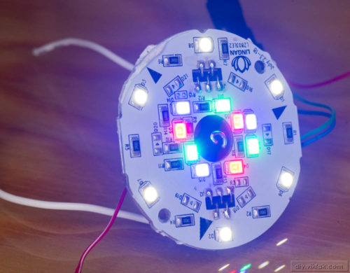
The white plastic cover came off just as easily as many have before and revealed a different design than many of the similar bulbs I had seen before. This bulb also had a small power supply separately, at the root (inside the screwy part) of the bulb, and a round PCB with all the logic and the LEDs on it.

The first thing I noticed is that this bulb was also based on the ESP8266 chip. This meant I had a fighting chance for at least finding out what problem it had.
On the board I also saw a few test points, so I prepared the troubleshooting process by finding out what each of them were connected to. As I suspected, they all corresponded to a specific pin of the ESP making it much easier to solder tiny, temporary cables to them rather than the ESP itself:

I also measured the voltage coming from the power supply, which was 12V DC. Temporarily, I removed those cables and attached my own power supply to the bulb which made the whole process safe as no mains voltage was involved from now on.
At this stage I could connect the bulb to a serial port on my computer and watch if it did something. And in fact, it was spitting out information once it was powered up. However, I couldn’t make any sense of it as I didn’t know what settings it was using to send data (speed, parity, stop bits…). I tried a few, then I gave it up, since I wasn’t really interested in what it was doing. I only wanted to see if it was working or it was completely dead. And it was very much alive!
Upgrade this, upgrade that
Next I tried to upload my own firmware that I had written a while ago for another design of mine, which, I knew, that with a few minor modifications should work on this bulb. The firmware uploaded without a problem for the first try, and after reboot, it was working with two minor problems, that I addressed next:
First, no LEDs were lit. I kinda expected this. The design I borrowed the code from used 4 specific GPIOs for controlling the LEDs. This bulb also used 4 specific GPIOs for the same purpose, however it would have been a huge coincidence if they had been the same! Well, it wasn’t. It so wasn’t, that none of the GPIOs used in the bulb matched any of the GPIOs I used in my other design. With a few trial and error, within a few minutes I was able to determine the correct GPIOs. The updated firmware now controlled all the 4 channels (red, green, blue, white) correctly.
Second, the LittleFS file system containing the configuration web pages proved to be too big, so it could not be uploaded to the bulb. This resulted in the device not serving web pages when connected to it. The cause of this is that the flash memory containing all the code was too small, i.e. 1MB. This also resulted in not being able to do Over-The-Air updates of the bulb, only serial updates. Just like in other devices, like this one, the solution was to replace the onboard SPI flash memory chip for a bigger one. The process was exactly the same, and this time I made a short video of doing it:
Once the board cooled down, I uploaded both the firmware and the file system and booted up the bulb.

This time, everything was working as expected:

Conclusion
To date it is not fully clear why the bulb was not working when it arrived from China. All its hardware components were OK, even its firmware was doing something, as verified by its serial output.
Anyway, I now have a fully functioning, open source, wifi smart light bulb running my own firmware, adding one more device to my home automation system.

Coowl shit bro! just had one of those lights break on me opened it up saw a blown capacitor replaced it and it worked and then I saw the esp32 like chip and was like we can do something with this and then if found your article!
currently designing a new housing for the lamp so I can make it an Ambilight kinda lamp
Cool idea! When you finish it, let me know here, would love to see it!