Introduction
A friend of mine asked me if I could jazz his Halo 4 Edition XBOX 360 wireless controller up a little bit in the short time he was visiting me. Originally, I offered to make this modification, but when I opened up his controller it soon became obvious that it’s not possible: in this new controller the color of the lights around the Guide button is not determined by the color of the LEDs. White LEDs are used and the plastic ring around the button filters the light, in this case, to blue. Not wanting to disappoint my friend, after some thinking I came up with this very simple addition to his controller.
The Idea
I didn’t want to use an arrangement where the lights would be on for an extended period of time, because that would lead to very short battery life in the controller. I also wanted this mod to be very easy to make, without microcontrollers or other kind of logic. To make things more challenging, I was not allowed to drill or modify in any way the existing controller cover.
So, after some brainstorming I got the idea to flash some lights inside the translucent controller case whenever the rumble motors are activated. This is a very simple, yet very cool looking (especially in a dark room) modification.
So, after some brainstorming I got the idea to flash some lights inside the translucent controller case whenever the rumble motors are activated. This is a very simple, yet very cool looking (especially in a dark room) modification.
Making of…
This is how I went about making the modifications:
- I removed the controller’s cover after unscrewing the 7 small screws that hold it together.
- I connected an oscilloscope to the rumble motors’ connections and did a test play. This was necessary to determine the polarity and amplitude of the signal that I wanted to use to drive the LEDs.
- Since I didn’t see anything special (some 3V pulses, that’s all) I understood I didn’t have to use any complicated circuitry to drive the LED.
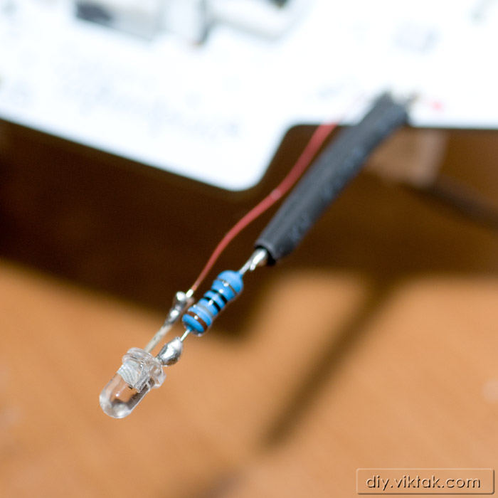
- I soldered a 180 ohm resistor on the anode of a 3mm red LED (color and size were my friend’s choice).

The anode and the resistor’s pin was trimmed to save space. - Using about 5 cm (2 inches) of AWG30 magnet wire I connected the LED and the rumble motor’s connections (observing polarity).
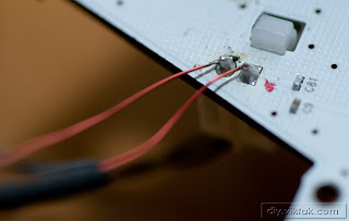
I marked the positive terminal of the rumble motor’s connector with a red marker. - I covered the sensitive parts of the assembly with heat shrink tube.

- I applied a small amount of hot glue on the solder joint at the rumble motor’s connection for extra mechanical strength.
- I repeated steps 4 to 7 for the second rumble motor.


The whole process took about 10 minutes to finish. After that some rigorous testing was needed and my friend gladly volunteered. 🙂
