
In your favorite online Chinese outlet the number of smart home gadgets/appliances seems to be growing on a daily basis. This is fantastic for home automation enthusiasts who want to automate their home or office. It is also beneficial for anyone with a very specific problem to solve. However, virtually 100% of these smart gadgets come with some major flaws, that I have already discussed in the past. Let’s recap:
- To control them you need to use proprietary software – to make things worse, you likely need a different app for each such device.
- You need to have an always on internet connection to operate them.
- You are locked into using the manufacturer’s servers which may or may not be there tomorrow. At this stage, there are several examples of businesses closing for one reason or another. As a result, thousands of customers are left unable to use their smart gadgets.
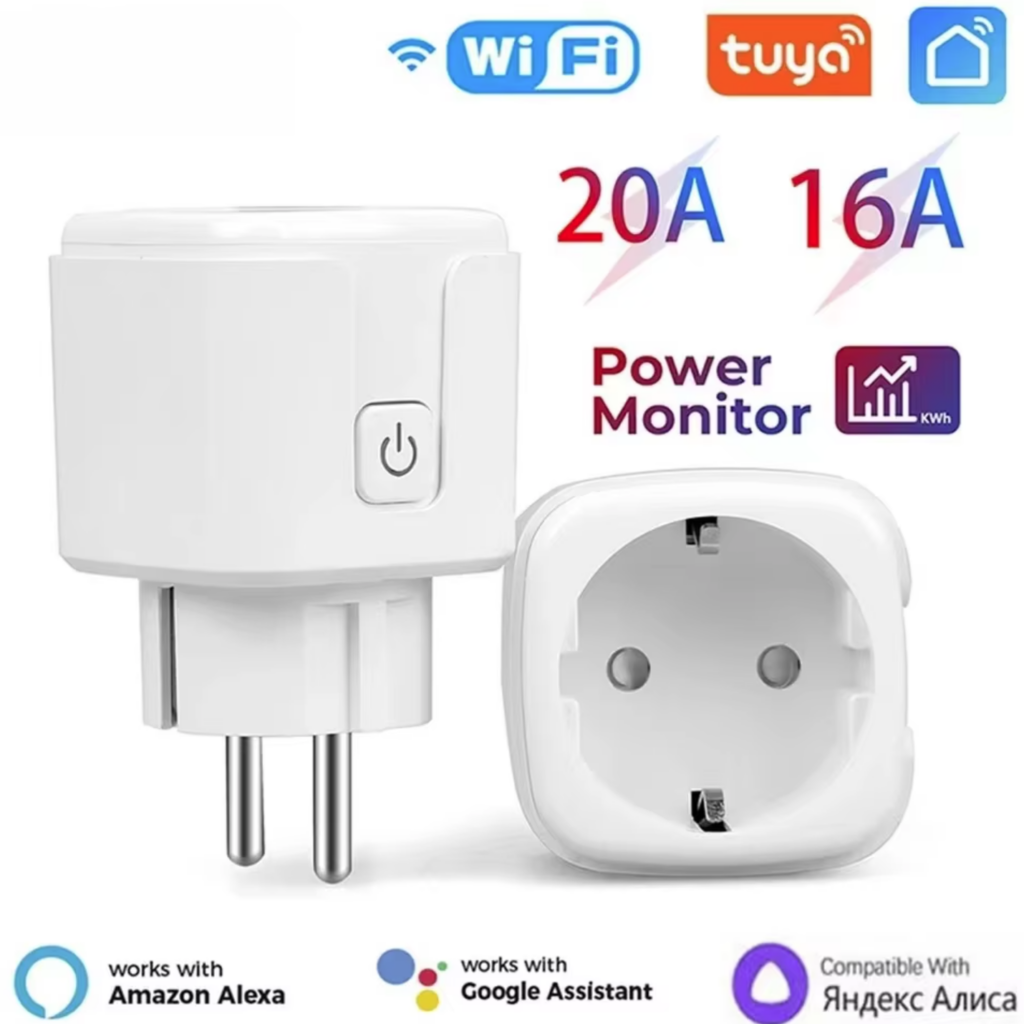
The solution for the above shortcomings is to use open source firmware in such devices. Of course, each model is different as such a different firmware is needed for each of them. Luckily, however, many smart devices are built around the same few microcontrollers. Over time, a few open source alternatives have emerged. Tasmota is one such firmware for ESPxxxx based devices. I have also created my own firmware for several ESPxxxx based devices, inlcuding my own creations. I have covered them in previous articles. This time I will cover another free and open source firmware called OpenBeken that is compatible with a variety of microcontrollers, such as the BK7231N, which I incidentally found in my latest purchase, a smart power socket:
Below I will show how I converted my smart plug with some basic tools and technique. It is now a privacy-friendly, user-friendly and automation-ready smart gadget.
The logical steps needed for the conversion are the same for each such device. However, all devices are different. Sometimes even when you buy two “identical” products, they turn out to be different on the inside. Thus, the actual steps may slightly be different.
Disassembly and finding the microcontroller
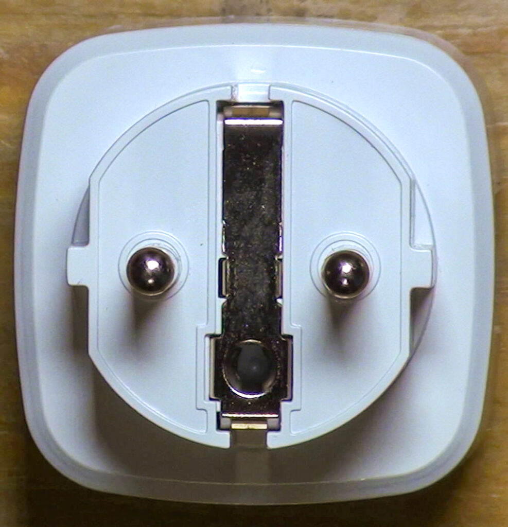
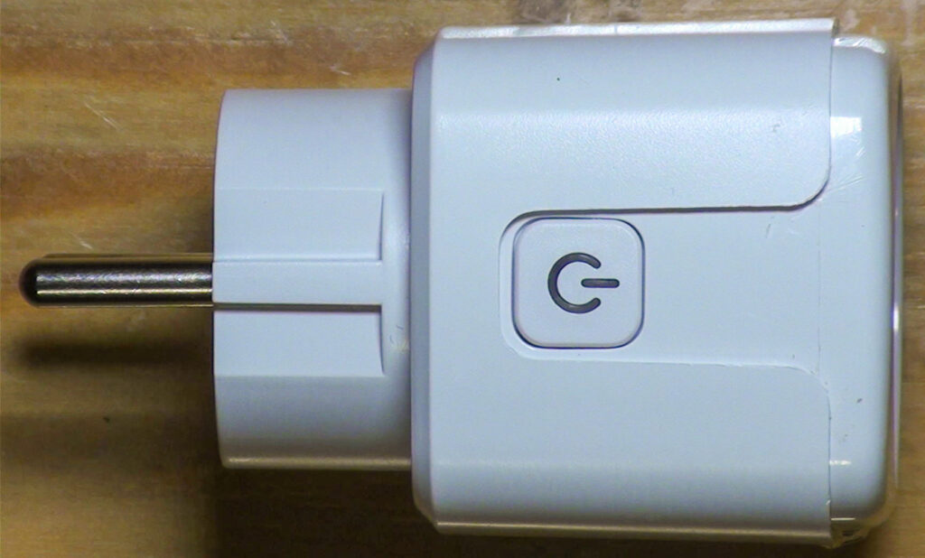
The first step is always to remove the device cover to get to the electronics. Here is a quick video showing how to open this particular socket:
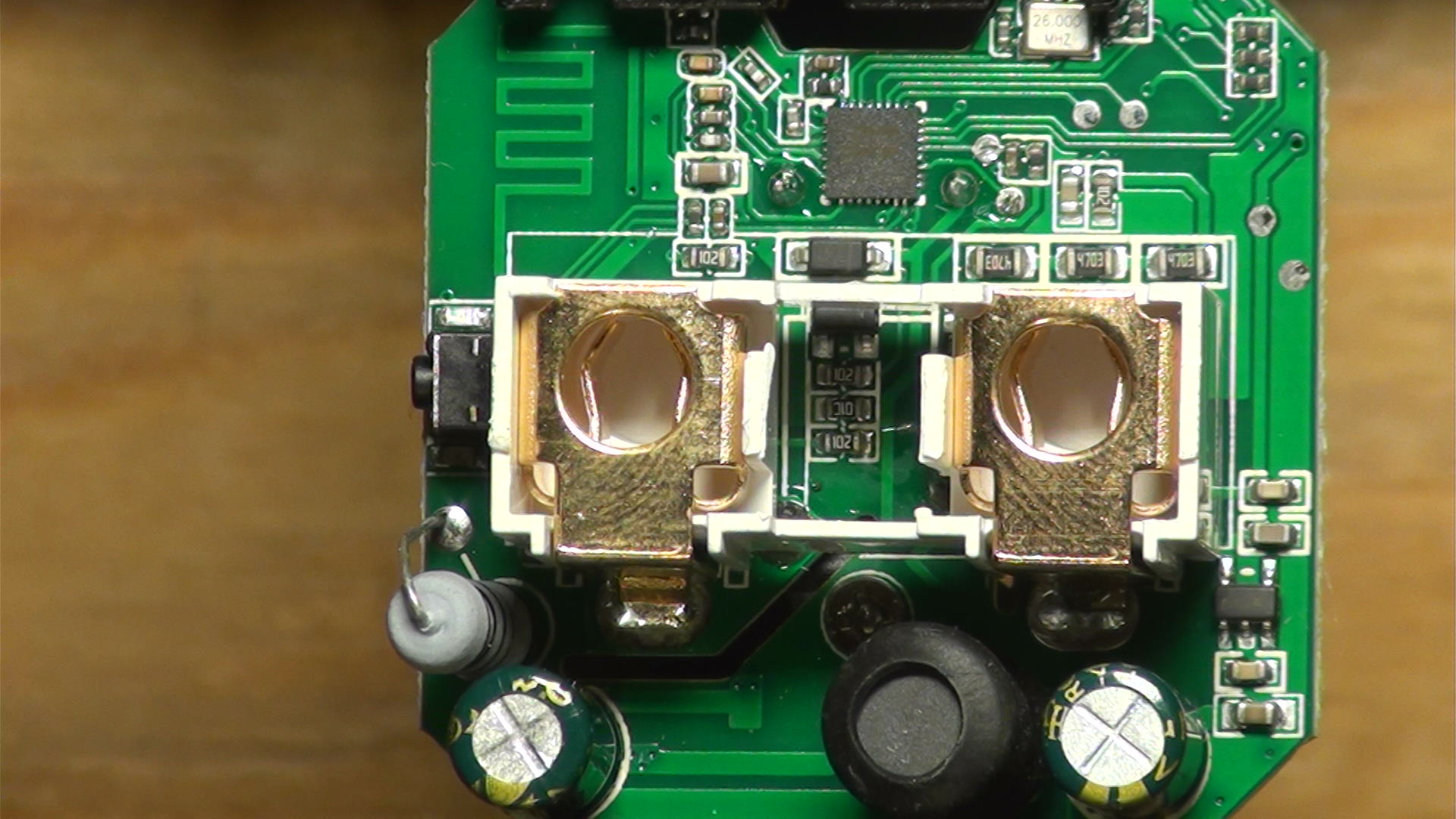
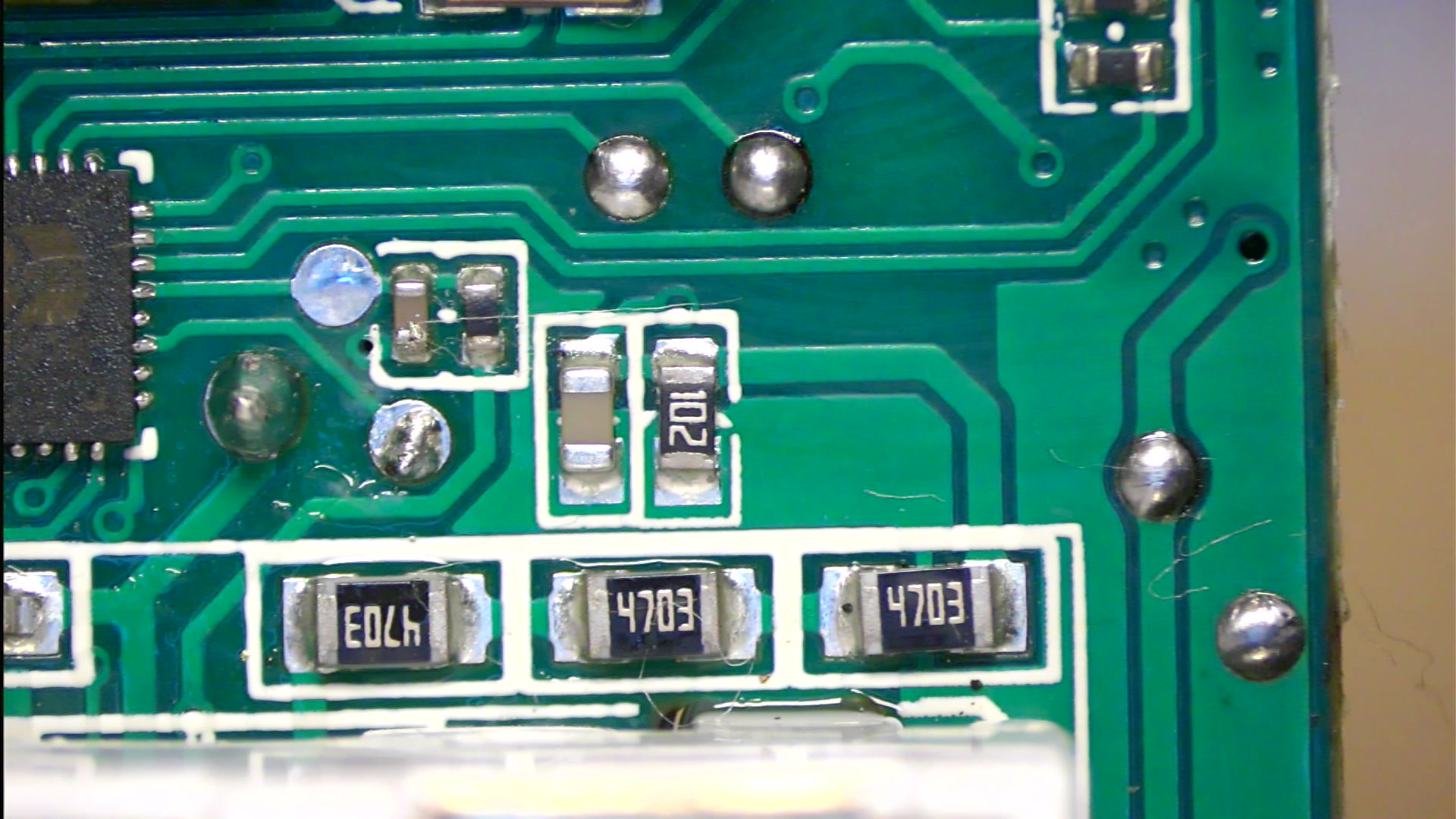
After getting physical access to the electronics, I had to identify some of the components on it. In this case, finding the MCU, the current sensor, the LEDs, the button was very simple. In some models additional disassembly is needed.
To program the MCU with the new firmware I also needed to locate a few traces on the PCB. In the case of the BK7231N, it is only 4 lines: GND, 3.3V, Tx and Rx. GND is the easiest to find: with a continuity meter find the point that is common across most capacitors. It is also, usually, the thickest trace on the PCB.
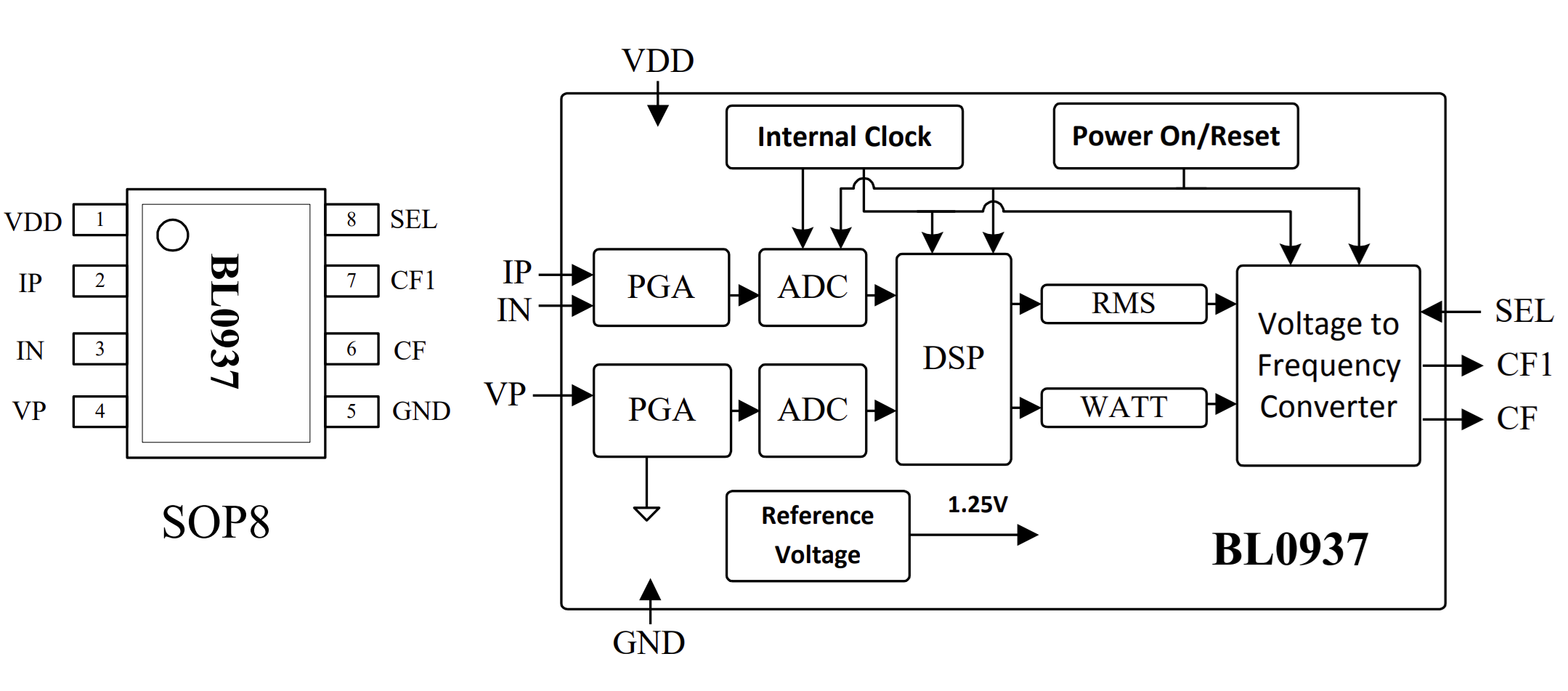
The rest of the lines I identified based on the datasheet:
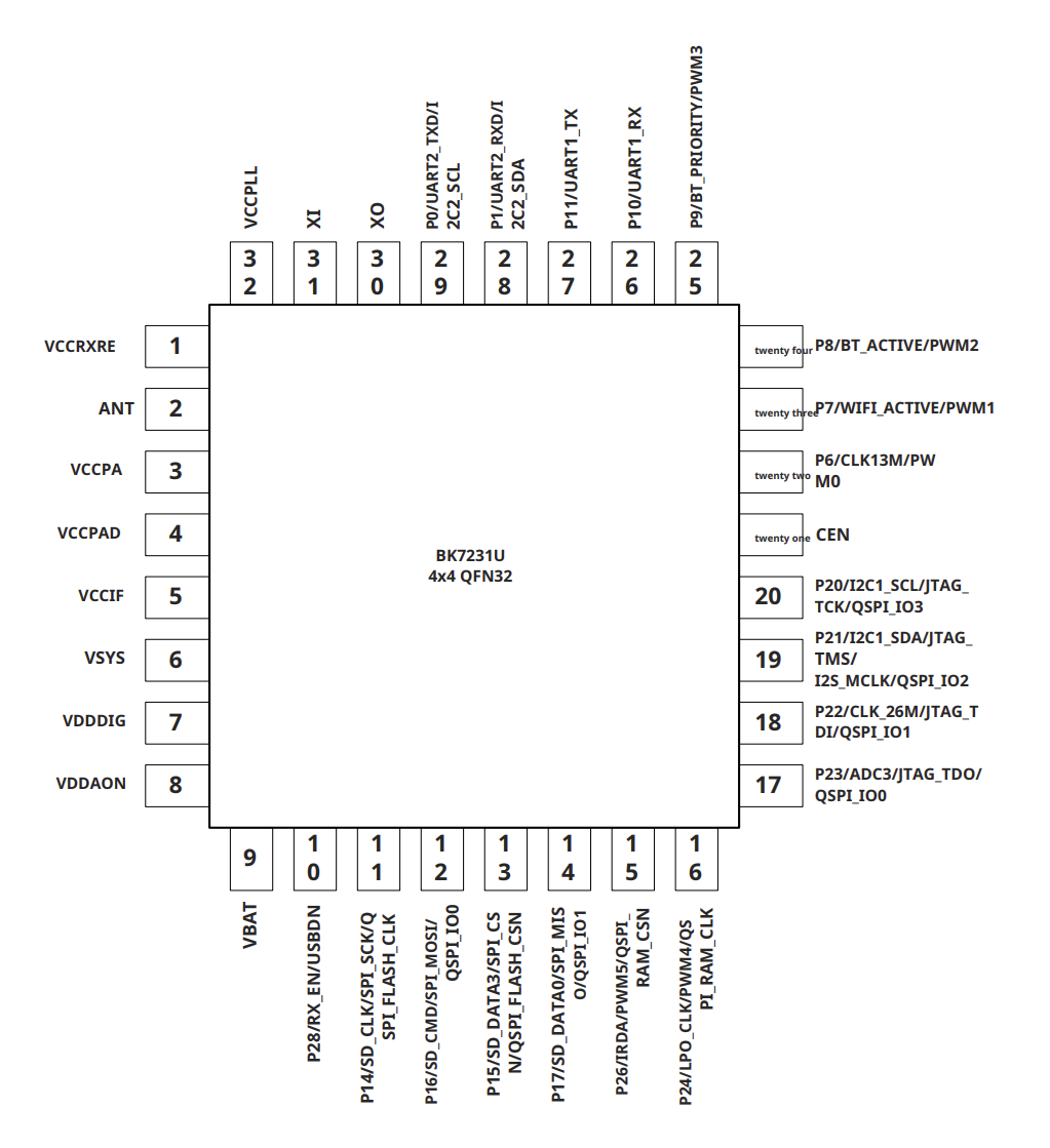
From the datasheet I learned that the MCU uses UART1 for programming, that is pins 26 (Rx) and 27 (Tx). The 3.3V power supply was a bit of a question mark for me at first as the chip has several power pins. Luckily, the datasheet clarifies that VBat is the chip’s main power line. I also found that VBat had a test point on the PCB – just like the 3 other lines:
Once I knew which test points did what, it was just a matter of soldering on some wires to get UART access to the MCU:
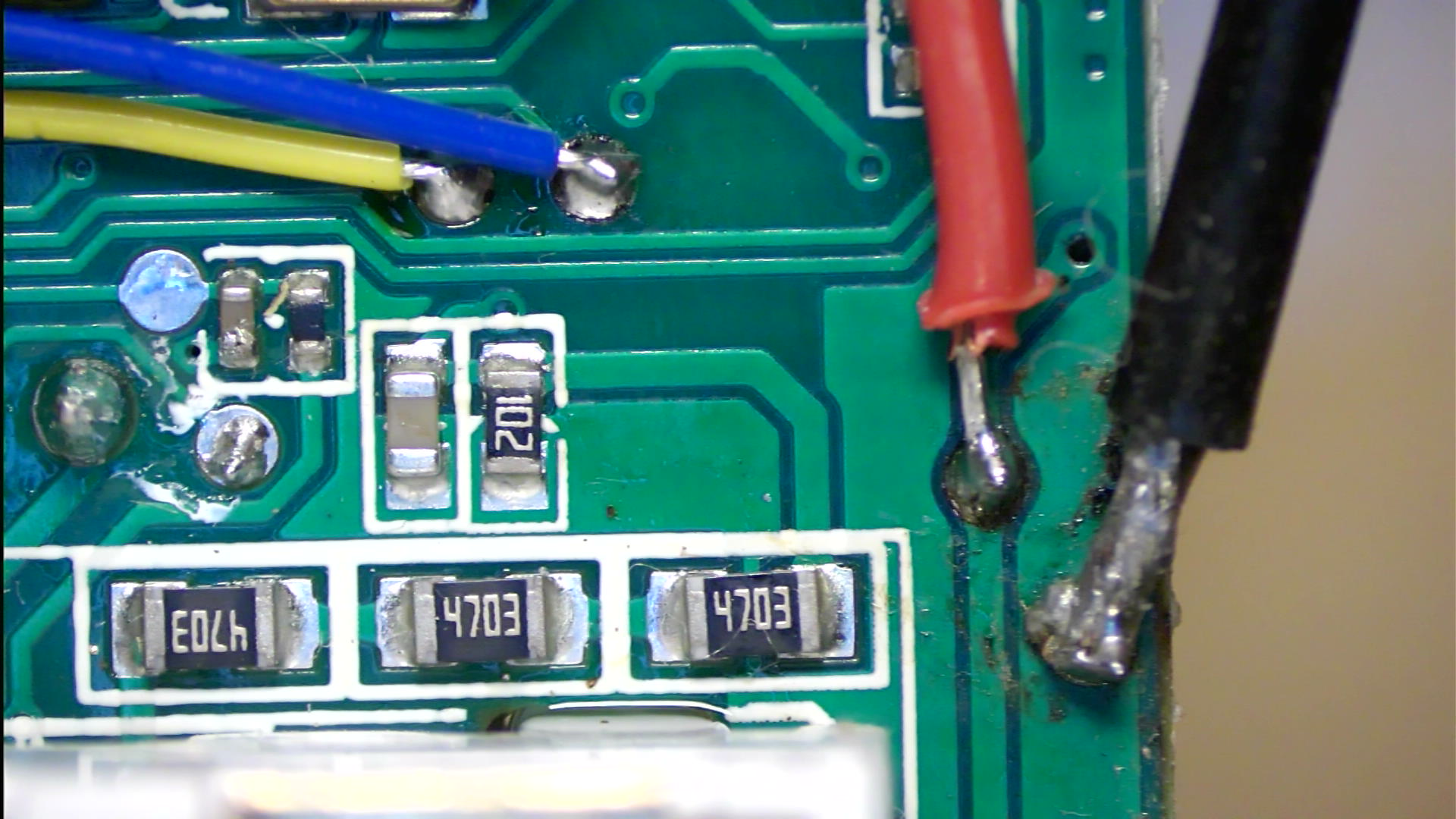
Here is the final layout:
- Black: GND
- Red: 3.3V
- Blue: UART1 – Tx
- Yellow: UART1 – Rx
A word of caution: the BK7231N has 2 UARTs: UART1 and UART2. In my experience, on some devices UART1 is used for programming the MCU and debugging messages are spat out on UART2, on some, like this one, UART1 is used for both.
Now I was ready to move onto the PC part of the game!
Backing up the original firmware
At this stage it is a good idea to verify that the UART connection between the PC and the MCU is working. For this I used a terminal emulator program – Putty. The communication settings were 115200 baud 8N1 – but this might be different for some other devices. Also, it speeds things up when I use the correct COM port….
Once everything is connected and configured, it was time to power up the device. If, instead of legible text you get random characters, you may need to set a different speed in Putty. If you don’t see anything, you may want to double check the connection and the COM port used.
V:BK7231N_1.0.1
REG:cpsr     spsr     r13      r14
SVC:000000D3          00401C1C 000033AC
IRQ:000000d2 00000010 00401e0c 44023354
FIR:000000d1 00000010 00401ffc dbbffa67
SYS:000000df          0040192c 00000158
ST:00000000
J 0x10000
bk_misc_init_start_type 0 0
prvHeapInit-start addr:0x4113d0, size:126000
[Flash]id:0xeb6015
[01-01 18:12:15 TUYA I][lr:0xa5969] mqc app init ...
[01-01 18:12:15 TUYA I][lr:0xb0977] thread_create name:sys_timer,stackDepth:4096,totalstackDepth:4096,priority:5
[01-01 18:12:15 TUYA D][lr:0xb0803] Thread:sys_timer Exec Start. Set to Running Stat
[01-01 18:12:15 TUYA I][lr:0xb0977] thread_create name:cmmod,stackDepth:4096,totalstackDepth:8192,priority:4
[01-01 18:12:15 TUYA D][lr:0xa5883] mq_pro:5 cnt:1
[01-01 18:12:15 TUYA D][lr:0xa5883] mq_pro:31 cnt:2
[01-01 18:12:15 TUYA D][lr:0xd5ad3] svc online log init success
[01-01 18:12:15 TUYA E][lr:0xccbf9] logseq empty
[01-01 18:12:15 TUYA I][lr:0xb0977] thread_create name:wk_th-0,stackDepth:5120,totalstackDepth:13312,priority:3
[01-01 18:12:15 TUYA E][lr:0xb48ed] wd_protected_read fails gw_bi -23
[01-01 18:12:15 TUYA D][lr:0xb4b5f] gw base read finish:-23
[01-01 18:12:15 TUYA D][lr:0xd368f] ty bt cmmod regist ok:1
dev id key: 16
d4 1d 8c d9 8f 00 b2 04 e9 80 09 98 ec f8 42 7e
[PLATFORM DEBUG]bt_port_init
[01-01 18:12:1ble mac:38-a5-c9-5b-17-5 TUYA N][lr:0xa1e59] bf2
!!!!!!init_type=0
le sdk re_inited
[01-01[ble_appm_send_gapm_res 18:12:15 TUYA D][lr:0xet_cmd]
!!!!!!init_type=1
llm_init:312
d40f[gapm_cmp_evt_handler] 5] bt active init
[01-conidx:0,operation:0x1,01 18:12:15 TUYA N][lr:status:0x0
cmd->addr.a0xd377d] ty bt sdk init ddr[5] :0
!!!!!!init_tsuccess finish
[01-01 ype=2
[gapm_cmp_evt_ha18:12:15 TUYA N][lr:0x5ndler] conidx:0,operatid093] < TUYA IOT SDK V:on:0x3,status:0x0
gapm2.3.3 BS:40.00_PT:2.2_L_cmp_evt:GAPM_SET_DEV_CAN:3.4_CAD:1.0.5_CD:1.0.ONFIG
gapm_cmp_evt:wai0 >
< BUILD AT:2022_12t GAPM_GEN_RAND_NB
_22[gapm_cmp_evt_handler] _14_55_08 BY ci_manage conidx:0,operation:0x1aFOR ty_iot_sdk AT bk723,status:0x0
gapm_cmp_e1n >
IOT DEFS < WIFI_Gvt:GAPM_GEN_RAND_NB
W:1[gapm_cmp_evt_handler]  DEBUG:1 KV_FILE:0 SHUTconidx:0,operation:0x1aDOWN_MODE:0 LITTLE_END:,status:0x0
gapm_cmp_e1 TLS_MODE:2 ENABLE_CLOvt:GAPM_GEN_RAND_NB
[gUD_OPERATION:0 OPERATINapm_cmp_evt_handler] conG_SYSTEM:2 ENABLE_SYS_Ridx:0,operation:0x28,stPC:0 RELIABLE_TRANSFER:atus:0x0
gapm_cmp_evt:0 ENABLE_LAN_ENCRYPTIONBLE_STACK_OK
[PLATFORM:1 ENABLE_LAN_LINKAGE:0 NOTICE]STACK INIT OK
 ENABLE_LAN_DEV:0 >

ble create new db
ble_e[01-01 18:12:15 TUYA N]nv->start_hdl = 0x10
[lr:0x5d09d] oem_bk7231n[PLATFORM NOTICE]CREATE_plug:1.1.17
[01-01 18 DB OK
:12:15 TUYA N][lr:0x5d0a7] firmware compiled at Jun 13 2023 20:36:20
[PLATFORM NOTIadv_state:1
[gapm_cmp_eCandler] conidx:0,operavt_handler] conidx:0,option:0x1b,status:0x0
eration:0x1b,status:0x0[01-01 18:12:15 TUYA N]
adv_actv_idx:0,tx_pwr:[lr:0x5d0bf] REST INFOR0
[PLATFORM DEBUG]UNKNMATION IS 0
[01-01 18:OW EVENT:17
[gapm_cmp_e12:15 TUYA N][lr:0x5c16vt_handler] conidx:0,opb] read oem cfg from uferation:0xa0,status:0x0file

[appm_adv_fsm_next] cur adv_state:1
auf read string is ,sel_d read string is ,sel_ppin_pin:26,rl1_lv:1,bt1_in_pin:26,rl1_lv:1,bt1_pin:24,net_trig:4,jv:1.pin:24,net_trig:4,jv:1.0.7,netled1_lv:0,netled0.7,netled1_lv:0,netled_reuse:0,ffc_select:0,n_reuse:0,ffc_select:0,nety_led:1,vi_pin:7,overety_led:1,vi_pin:7,over__cur:25000,resistor:1,bcur:25000,resistor:1,btt1_lv:0,reset_t:5,netle1_lv:0,reset_t:5,netledd1_pin:23,chip_type:0,l1_pin:23,chip_type:0,loose_vol:75,over_vol:255se_vol:75,over_vol:255,m,module:CB2S,ele_pin:6,odule:CB2S,ele_pin:6,[b[01-01 18:12:15 TUYA N]le_appm_set_adv_data]se[lr:0x5be67] ,over_vol:t data
end adv_state:2 is 255
[01-01 18:12:
[PLATFORM DEBUG]UNKNO15 TUYA N][lr:0x5be67] ,W EVENT:16
[gapm_cmp_elose_vol: is 75
[01-0vt_handler] conidx:0,op1 18:12:15 TUYA N][lr:0eration:0xa9,status:0x0x5be67] ,over_cur: is 2
[appm_adv_fsm_next] c5000
[01-01 18:12:15 Tur adv_state:2
adv_staUYA N][lr:0x5bec1] ,chite:3
end adv_state:3
p_type: is 0
[01-01 1[PLATFORM DEBUG]UNKNOW 8:12:15 TUYA N][lr:0x5bEVENT:16
[gapm_cmp_evtec1] ,ele_fun_en: is 1 _handler] conidx:0,opera
[01-01 18:12:15 TUYA tion:0xaa,status:0x0
[N][lr:0x5be67] ,ele_pinappm_adv_fsm_next] cur : is 6
[01-01 18:12:1adv_state:3
adv_state:5 TUYA N][lr:0x5be67] ,6
[ble_appm_start_advervi_pin: is 7
[01-01 1tising]
end adv_state:8:12:15 TUYA N][lr:0x5b6
[PLATFORM DEBUG]UNKNe67] ,sel_pin_lv: is 1 OW EVENT:16
[gapm_cmp_
evt_handler] conidx:0[01-01 18:12:15 T,operaUYA N][lr:0x5be67] ,sel_tion:0xa4,status:0x0
[pin_pin: is 26
[01-01appm_adv_fsm_next] cur  18:12:15 TUYA N][lr:0xadv_state:6
adv_state:5be67] ,resistor: is 1 7
end adv_state:7
[PL
[01-01 18:12:15 TUYA NATFORM DEBUG]UNKNOW EVE][lr:0x5bec1] ,vol_def:NT:16
 is 0
[01-01 18:12:15 TUYA N][lr:0x5bec1] ,ffc_select: is 0
[01-01 18:12:15 TUYA N][lr:0x5bec1] ,jv: is 1.0.7
[01-01 18:12:15 TUYA N][lr:0x5bec1] ,module: is CB2S
[01-01 18:12:15 TUYA N][lr:0x5bec1] ,net_trig: is 4
[01-01 18:12:15 TUYA N][lr:0x5be67] ,netled1_lv: is 0
[01-01 18:12:15 TUYA N][lr:0x5be67] ,netled1_pin: is 23
[01-01 18:12:15 TUYA N][lr:0x5bec1] ,nety_led: is 1
[01-01 18:12:15 TUYA N][lr:0x5bec1] ,netn_led: is 0
[01-01 18:12:15 TUYA N][lr:0x5bec1] ,netled_reuse: is 0
[01-01 18:12:15 TUYA N][lr:0x5be67] ,reset_t: is 5
[01-01 18:12:15 TUYA N][lr:0x5bec1] ,ch1_stat: is 2
[01-01 18:12:15 TUYA N][lr:0x5be67] ,ch_num: is 1
[01-01 18:12:15 TUYA N][lr:0x5bd47] channal num is 1
[01-01 18:12:15 TUYA N][lr:0x5c047] ,rl1_lv: is 1
[01-01 18:12:15 TUYA N][lr:0x5c047] ,rl1_pin: is 8
[01-01 18:12:15 TUYA N][lr:0x5c047] ,bt1_lv: is 0
[01-01 18:12:15 TUYA N][lr:0x5c047] ,bt1_pin: is 24
[01-01 18:12:15 TUYA N][lr:0x5c047] ,ch_dpid1: is 1
[01-01 18:12:15 TUYA N][lr:0x5c047] ,ch_cddpid1: is 9
[01-01 18:12:15 TUYA N][lr:0x5c7e9] product have measure , chip is 0 vol is 2200  res is 1
[01-01 18:12:15 TUYA N][lr:0xcac1b] key_addr: 0x1ee000   block_sz 4096
[01-01 18:12:15 TUYA N][lr:0xcaceb] get key:
0xdb 0xe5 0xf5 0xde 0x2a 0x14 0x41 0x6a 0xbe 0x3e 0xfa 0x8d 0xb6 0x43 0xbe 0xf8
[load]bandgap_calm=0x67->0x27,vddig=4->5
IP Rev: ebc6695
[bk]tx_txdesc_flush
[FUNC]intc_init
[FUNC]calibration_main
gpio_level=1,txpwr_state=0
get rfcali_mode:1
calibration_main over
temp in flash is:350
xtal in flash is:12
[FUNC]func_init_extended OVER
Version:
tcp_port:62642
app_init finished
[01-01 18:12:16 TUYA N][lr:0x5b9f5] mf_init succ
[01-01 18:12:16 TUYA N][lr:0x5db89] init wfled
[01-01 18:12:16 TUYA N][lr:0x5dbcf] [switch] wifi led init ok
[01-01 18:12:16 TUYA E][lr:0x566f3] OPRT_INVALID_PARM
[01-01 18:12:16 TUYA N][lr:0x5f8fb] RLY TYPE IS 0
[01-01 18:12:16 TUYA N][lr:0x5dc2d] channel 0 Init ok
[01-01 18:12:16 TUYA N][lr:0x5dd91] tuya_ele_hw_init success
[01-01 18:12:16 TUYA N][lr:0x5cd0f] need scan ssid: tuya_mdev_test2 to enter product test repeatedly.
[01-01 18:12:16 TUYA N][lr:0x5ba61] current product ssid name:tuya_mdev_test2
[sa_sta]MM_RESET_REQ
[bk]tx_txdesc_flush
[sa_sta]ME_CONFIG_REQ
[sa_sta]ME_CHAN_CONFIG_REQ
[sa_sta]MM_START_REQ
sizeof(wpa_supplicant)=928
hapd_intf_add_vif,type:2, s:0, id:0
wpa_dInit
enter low level!
mac 38:a5:c9:5b:17:f1
leave low level!
net_wlan_add_netif done!, vif_idx:0
scan SSID: 74 75 79 61 5F 6D 64 65 76 5F 74 65 73 74 32
wpa_supplicant_req_scan
Setting scan[retry16] request: 0.000000 sec
wpa_supplicant_scan
wpa_supplicant_scan 866
wpa_drv_scan
ht in scan
scan_start_req_handler
wpa_driver_scan_start_cb
temperature_type=2
temp_code:22 - adc_code:357 - adc_trend:[13]:350->[12]:360
wpa_driver_scan_cb
Scan completed in 2.342000 seconds
[PLATFORM ERROR]scan err
[01-01 18:12:18 TUYA N][lr:0x5cd41] frame goto init!
[01-01 18:12:18 TUYA N][lr:0xb9c7b] wifi soc init. pid:keyjup78v54myhan firmwarekey:keyjup78v54myhan ver:1.1.17
[PLATFORM NOTICE]bk_rst:0 tuya_rst:0
[01-01 18:12:18 TUYA N][lr:0xb3d9f] Last reset reason: 0
[01-01 18:12:18 TUYA N][lr:0xb3e7b] serial_no:38a5c95b17f1
rw_ieee80211_set_country code:
code: CN
channel: 1 - 13
mode: MANUAL
bk_wlan cca closed
[01-01 18:12:18 TUYA N][lr:0xb3eb9] gw_cntl.gw_wsm.stat:0
[01-01 18:12:18 TUYA N][lr:0xb847d] gw_cntl->gw_wsm.nc_tp:1
[01-01 18:12:18 TUYA N][lr:0xb8485] gw_cntl->gw_wsm.md:0
[01-01 18:12:18 TUYA N][lr:0xb4015] gw_cntl.gw_if.abi:0 input:0
[01-01 18:12:18 TUYA N][lr:0xb4023] gw_cntl.gw_if.product_key:keyjup78v54myhan, input:keyjup78v54myhan
[01-01 18:12:18 TUYA N][lr:0xb402d] gw_cntl.gw_if.tp:0, input:0
[01-01 18:12:18 TUYA N][lr:0xb403d] gw_cntl.gw_if.firmware_key:keyjup78v54myhan, input:keyjup78v54myhan
[01-01 18:12:18 TUYA N][lr:0xd37fb] ty bt upd product:keyjup78v54myhan 1
[01-01 18:12:18 TUYA E][lr:0xd66a1] uf_open LIGHT_MODE err 8
[01-01 18:12:18 TUYA E][lr:0x5a6c7] uf file LIGHT_MODE can't open and read data!
[01-01 18:12:18 TUYA E][lr:0xd66a1] uf_open RLY_INIT err 8
[01-01 18:12:18 TUYA E][lr:0x5a6c7] uf file RLY_INIT can't open and read data!
[01-01 18:12:18 TUYA N][lr:0x5dff7] tuya_get_relay_init_type is 2
[01-01 18:12:18 TUYA N][lr:0x5e265] __read_saved_stat
[01-01 18:12:18 TUYA E][lr:0x5eadf] ch_idx:[0] is over!
[01-01 18:12:18 TUYA E][lr:0x5eadf] ch_idx:[0] is over!
[01-01 18:12:18 TUYA E][lr:0x582a1] input over range
[01-01 18:12:18 TUYA N][lr:0x584a9] start tuya_inch_time_init..
[01-01 18:12:18 TUYA N][lr:0x58527] init read inch info is null!
[01-01 18:12:18 TUYA N][lr:0x5ea21] init read quick info is null!
[01-01 18:12:18 TUYA N][lr:0x5a3d3] get prod test result!:1
[01-01 18:12:18 TUYA N][lr:0x5a55d] dltj start success
[01-01 18:12:18 TUYA N][lr:0x5ce8b] tuya_measure_chip ok
[01-01 18:12:18 TUYA E][lr:0xd66a1] uf_open temp_energy err 8
[01-01 18:12:18 TUYA E][lr:0x5a6c7] uf file temp_energy can't open and read data!
[01-01 18:12:18 TUYA N][lr:0x5a923] LOAD NO TIME energy : 0
[01-01 18:12:18 TUYA E][lr:0xd66a1] uf_open day_energy err 8
[01-01 18:12:18 TUYA E][lr:0x5a6c7] uf file day_energy can't open and read data!
[01-01 18:12:18 TUYA N][lr:0x5a941] have storage ele data:-1
[01-01 18:12:18 TUYA N][lr:0x5a95f] LOAD loc_data_energy : 0
[01-01 18:12:18 TUYA N][lr:0x5a969] LOAD loc_data_time : 0
[01-01 18:12:18 TUYA N][lr:0x5a95f] LOAD loc_data_energy : 0
[01-01 18:12:18 TUYA N][lr:0x5a969] LOAD loc_data_time : 0
[01-01 18:12:18 TUYA N][lr:0x5a95f] LOAD loc_data_energy : 0
[01-01 18:12:18 TUYA N][lr:0x5a969] LOAD loc_data_time : 0
[01-01 18:12:18 TUYA N][lr:0x5a95f] LOAD loc_data_energy : 0
[01-01 18:12:18 TUYA N][lr:0x5a969] LOAD loc_data_time : 0
[01-01 18:12:18 TUYA N][lr:0x5a95f] LOAD loc_data_energy : 0
[01-01 18:12:18 TUYA N][lr:0x5a969] LOAD loc_data_time : 0
[01-01 18:12:18 TUYA N][lr:0x5a95f] LOAD loc_data_energy : 0
[01-01 18:12:18 TUYA N][lr:0x5a969] LOAD loc_data_time : 0
[01-01 18:12:18 TUYA N][lr:0x5a95f] LOAD loc_data_energy : 0
[01-01 18:12:18 TUYA N][lr:0x5a969] LOAD loc_data_time : 0
[01-01 18:12:18 TUYA N][lr:0x5a95f] LOAD loc_data_energy : 0
[01-01 18:12:18 TUYA N][lr:0x5a969] LOAD loc_data_time : 0
[01-01 18:12:18 TUYA N][lr:0x5a95f] LOAD loc_data_energy : 0
[01-01 18:12:18 TUYA N][lr:0x5a969] LOAD loc_data_time : 0
[01-01 18:12:18 TUYA N][lr:0x5a95f] LOAD loc_data_energy : 0
[01-01 18:12:18 TUYA N][lr:0x5a969] LOAD loc_data_time : 0
[01-01 18:12:18 TUYA E][lr:0xd66a1] uf_open over_charge err 8
[01-01 18:12:18 TUYA E][lr:0x5a6c7] uf file over_charge can't open and read data!
[01-01 18:12:18 TUYA N][lr:0x5ae47] read overcharge function:0
[01-01 18:12:18 TUYA N][lr:0x5cecd] tuya_dltj_init ok
[01-01 18:12:18 TUYA N][lr:0x5717d] wd_common_read failed op_ret:-6
[01-01 18:12:18 TUYA N][lr:0x5717d] wd_common_read failed op_ret:-6
[01-01 18:12:18 TUYA N][lr:0x5717d] wd_common_read failed op_ret:-6
[01-01 18:12:18 TUYA N][lr:0x5d017] device_init ok  free_mem_size:56144
wpa_supplicant_req_scan
Setting scan[retry16] request: 0.000000 sec
wpa_supplicant_scan
wpa_supplicant_scan 866
wpa_drv_scan
ht in scan
scan_start_req_handler
wpa_driver_scan_start_cb
RSSI: c0:05:c2:ef:94:79  -58 -> -57
temp_code:25 - adc_code:351 - adc_trend:[12]:360->[13]:350
wpa_driver_scan_cb
Scan completed in 2.350000 seconds
net_wlan_remove_netif done!, vif_idx:0
Cancelling scan request
scanu completed
Soft_AP_start
[saap]MM_RESET_REQ
[bk]tx_txdesc_flush
[saap]ME_CONFIG_REQ
[saap]ME_CHAN_CONFIG_REQ
[saap]MM_START_REQ
apm start with vif:0
me_set_ps_disable:842 0 0 1 0 0
------beacon_int_set:100 TU
set_active param 0
[msg]APM_STOP_CFM
update_ongoing_1_bcn_update
hal_machw_enter_monitor_mode
[01-01 18:12:21 TUYA N][lr:0x5f483] net stat 1 change free_mem_size:62568
[01-01 18:12:21 TUYA N][lr:0xa1d2f] update bound stat:0
dev id key: 16
66 05 f3 a5 f8 95 9e 7f 93 92 22 5b c6 40 9f 90
[PLATFORM DEBUG]bt rst adv
adv_state:12
[gapm_cmp_evt_handler] conidx:0,operation:0xa9,status:0x0
[appm_adv_fsm_next] cur adv_state:c
adv_state:13
end adv_state:d
[PLATFORM DEBUG]UNKNOW EVENT:19
[PLATFORM DEBUG]UNKNOW EVENT:16
[gapm_cmp_evt_handler] conidx:0,operation:0xaa,status:0x0
[appm_adv_fsm_next] cur adv_state:d
adv_state:7
end adv_state:7
[PLATFORM DEBUG]UNKNOW EVENT:20
[PLATFORM DEBUG]UNKNOW EVENT:16
[01-01 18:12:21 TUYA N][lr:0xa1b01] ble adv && resp changed
[01-01 18:12:23 TUYA E][lr:0x5b115] tuya_fault_event_upload op_ret:-1
The recommended tool for tinkering with the BK7231N (and several other similar MCUs) is an open source tool called BK7231 GUI Flash Tool. It has a lot of features of which we only need to use a few for this task.
First, I created a backup of the original firmware. In case something goes wrong, I should be able to go back to the factory firmware and start over.
It is a good idea to extract the settings (i.e. the hardware setup) from the original firmware. We can do this on this page:
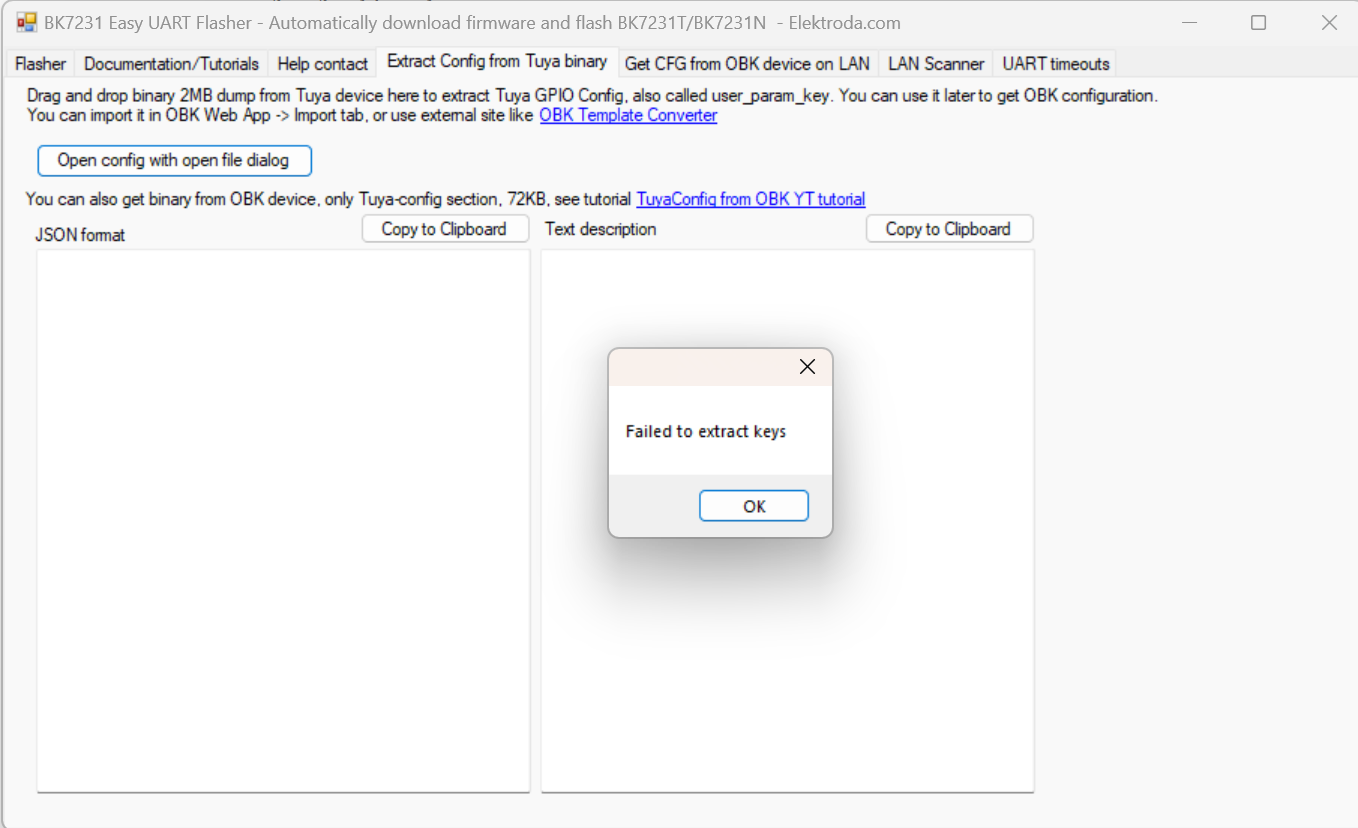
This did not work for me, so I had to figure out the sockets configuration another way. If it works for you, then it’s great! If not, don’t despair, there are other ways to figure it out. More about this later.
Flashing new firmware
In the same tool, first I selected the COM port, the chip type, then downloaded the latest firmware:
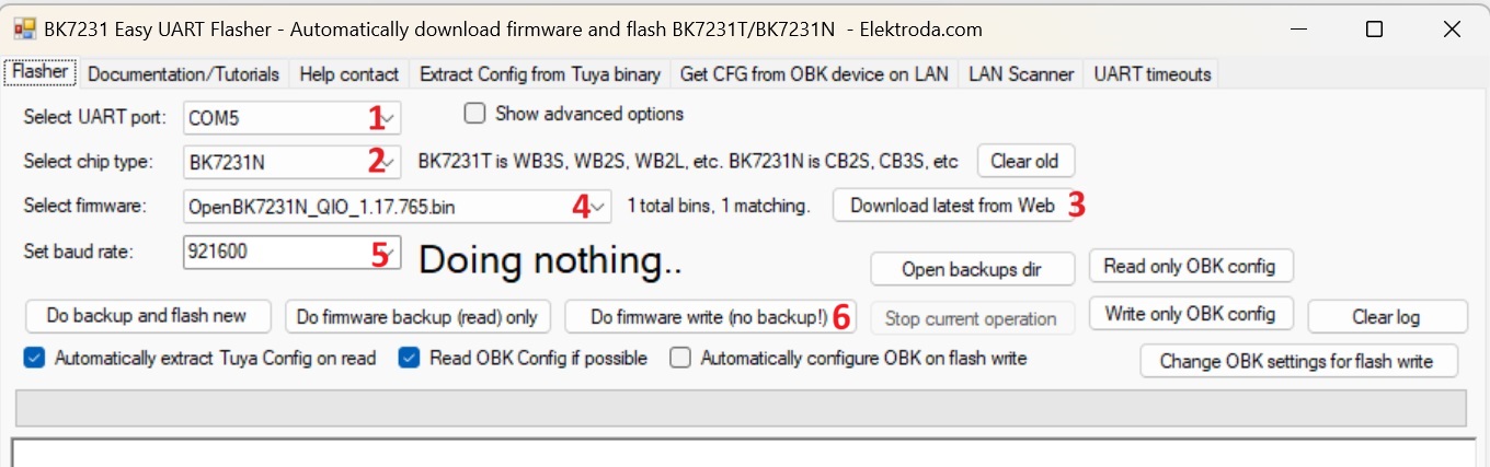
It is worth mentioning, at least for people like me, who come from an ESP background, that the BK7231 family of chips don’t use a special pin to put the device in “download” mode. The BK7231 enters “download” mode on every re/start for a few milliseconds, so the flashing works like this: Click the Do firmware write button, then apply power to the MCU. It might take a few tries to get the timing right, but it is nothing to worry about it. Alternatively, you can ground the CEN pin of the MCU for a reset.
The flashing process takes about a minute – do not interrupt it. After a successful flashing, it was time for restarting the device with its fresh firmware.
Note, that this step and the previous one could have been done at the same time, but I like keeping things simple, one thing at a time.
Once the programming was done, I removed the small wires.
First time configuration
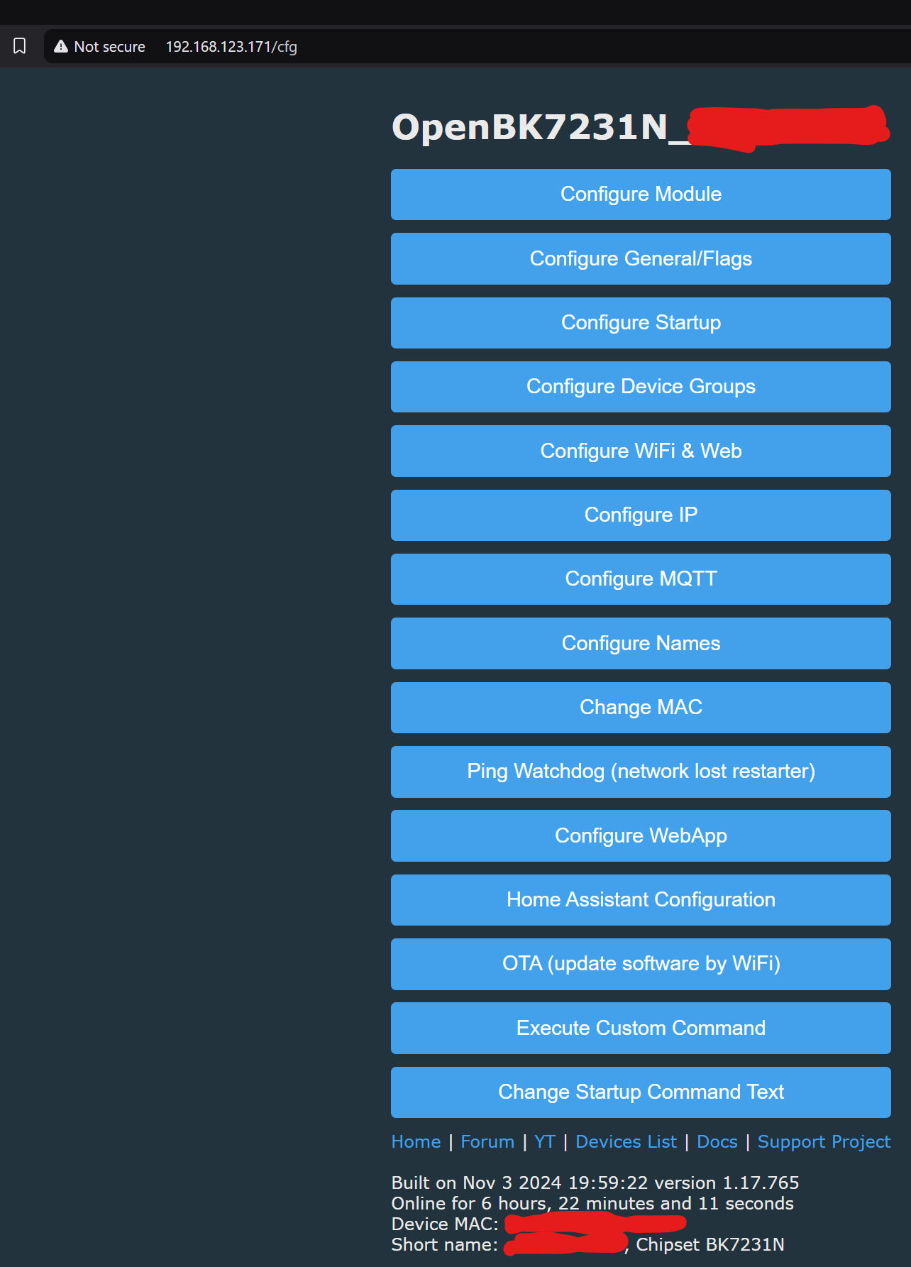
After flashing the new firmware, the device is in default state, and creates an open, unsecure access point with a name like OpenBK7231N_********, where the stars are placeholders for the device’s MAC address. I connected to it using my phone and browsed to the http://192.168.4.1 address where OpenBeken’s configuration page was waiting for me.
If you are used to Tasmota, this screen is very familiar to you. If not, the user interface is very clean and intuitive. The first (and only) thing I did here is to connect to my home’s WiFi network. After reboot, the device connected to my home WiFi network and the rest of the configuration followed.
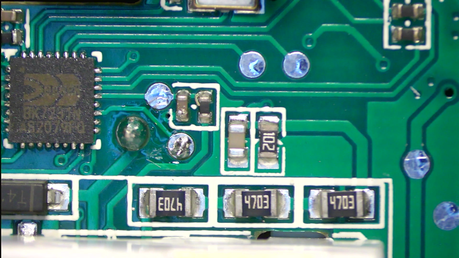
Next, the firmware needed to be configured to the specific device, a smart plug with power metering. For this I used the built-in web app, which can be launched from device’s home page by clicking Launch Web Application. The GPIO Finder is a great aid in finding out what GPIO does what on the board. It is not suitable for everything, but it at least takes out the guesswork from finding the basic controls, i.e. buttons, LEDs, relays. So finding out the relay and LEDs was relatively easily using this built-in tool, but finding out the current sensor’s interface needed another approach: What I did was I had a closer look at the PCB and traced the 3 signals from the current sensor to the MCU.

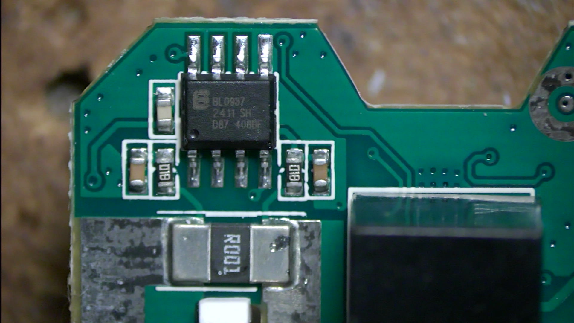
According to the datasheet of the BL0937 current sensor, it uses three lines for communicating with the MCU: CF, CF1 and SEL.
Using a conductivity meter, I traced all 3 signals back to the MCU, to fill out the missing details in the config page of the WebApp. After saving the settings and restarting the unit, some of the features of the smart plug were working, but not the power metering. After some investigation, I kind of gave it up for the day, and asked for help on the OpenBeken community forum. Within minutes, I got help from someone more experienced with these modules. A big thank you to [diwadiow] for helping me!! I learned, that from the original bootlog (before the conversion) it is possible to figure out what GPIOs are used for what. Of the bootlog example (earlier) this is the relevant part that describes the GPIO configuration:
sel_ppin_pin:26,rl1_lv:1,bt1_in_pin:26,rl1_lv:1,bt1_pin:24,net_trig:4,jv:1.pin:24,net_trig:4,jv:1.0.7,netled1_lv:0,netled0.7,netled1_lv:0,netled_reuse:0,ffc_select:0,n_reuse:0,ffc_select:0,nety_led:1,vi_pin:7,overety_led:1,vi_pin:7,over__cur:25000,resistor:1,bcur:25000,resistor:1,btt1_lv:0,reset_t:5,netle1_lv:0,reset_t:5,netledd1_pin:23,chip_type:0,l1_pin:23,chip_type:0,loose_vol:75,over_vol:255se_vol:75,over_vol:255,m,module:CB2S,ele_pin:6,odule:CB2S,ele_pin:6,This results in a configuration like this for my device:
{
  "vendor": "Tuya",
  "bDetailed": "0",
  "name": "Full Device Name Here",
  "model": "enter short model name here",
  "chip": "BK7231N",
  "board": "TODO",
  "flags": "1024",
  "keywords": [
    "TODO",
    "TODO",
    "TODO"
  ],
  "pins": {
    "6": "BL0937CF;0",
    "7": "BL0937CF1;0",
    "8": "Rel;1",
    "23": "WifiLED_n;0",
    "24": "Btn;1",
    "26": "BL0937SEL;0"
  },
  "command": "backlog StartDriver bl0937;StartDriver NTP;SetupEnergyStats 1 60 60 1",
  "image": "https://obrazki.elektroda.pl/YOUR_IMAGE.jpg",
  "wiki": "https://www.elektroda.com/rtvforum/topic_YOUR_TOPIC.html"
}
In the pins section, you can see the pin definitions. The command section is a startup command that is run every time the device powers up. In this case, it ensures the power meter and NTP modules start. This allows power metering and proper time keeping.
If you happen to have the same model, you can import these settings in your smart plug and it will work after a reboot.
At this the smart plug is configured correctly for basic operation. If you want to configure further options, like MQTT, Home Assistant integration, you can do that on the main configuration page:
You may ask, how come the configuration was different to what I found by tracing the signals on the PCB. Well, it turns out, that I didn’t identify pin #1 of the MCU correctly, so all my measurements were 8 pins offset… Once I deducted 8 of each value, my results were the same as the configuration [diwadiow] helped me with…
Conclusion
This was my first experience with the BK7231N MCU and also with OpenBeken. I found this conversion easy to make and totally worth it. There are so many cheap smart devices are available on the market, and you can convert most of them like this and make them privacy friendly. So what are you waiting for? Go get one yourself and start experimenting – I’ll be here if you need any help along the way!

Pingback: Tuya WiFi-IR Remote Conversion to Open Source – Walkthrough – Viktor’s DIY Blog
Pingback: Tuya PIR Sensor Conversion to Open Source – Walkthrough – Viktor’s DIY Blog