Introduction
I usually make a custom PCB for my electronic projects. Throughout development the PCB, however, changes several times. Making a custom PCB at each stage is not practical for several reasons including price, long waiting times between versions and being very wasteful. For all these reasons I use a test board/breadboard/prototype board that can be changed easily and instantly before development reaches a final stage.
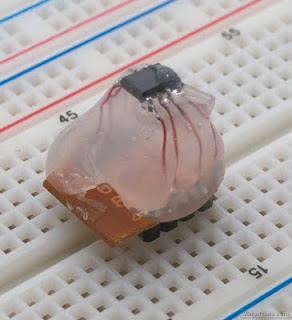 |
| The finished blob is comfortable seated in a test board. |
Problem
There is one problem with this approach: test boards are designed to take TTH (through the hole) components and cannot take SMT parts. I usually use SMT parts to make my PCBs as small as possible, so the solution for me so far has been to buy both SMT and TTH versions of a chip, use one for development and the other for the final product. This has been working for me for quite some time, but now I am in a situation where the manufacturer doesn’t make TTH version of a particular chip.
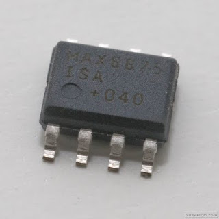 |
| In this case I was using the 8 pin SOIC version of MAX6675. |
Solution
To overcome this problem I came up with a quick and dirty solution: I solder thin copper wires to each of the pins of the chip and connect them to some pin headers that are soldered in a piece of breadboard. The advantage of this method is that it can be done to almost any chip, doesn’t require special resources and creates a very durable design that – so far – seems indestructible. The only disadvantage is that the chip that is “converted” into TTH cannot be used for anything else afterwards. This is not a big problem for me as I always buy more parts than I actually need (just in case I mess up something…).
Materials needed
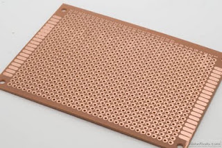 |
| A piece of solder-in prototype board |
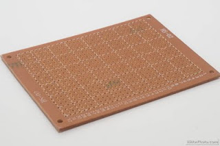 |
| Front/Component side of the prototype board |
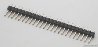 |
| Straight type pin header – cut to match the number of pins of the chip |
I also used the following items:
- AWG 35 laminated copper wire
- soldering iron/solder
- hot glue
- sharp knife of saw to cut the breadboard to size
Build steps

- Pre-solder all the pins of the chip
- Solder about 2-3 cm (1 inch) insulated copper cable to each pin
- Cut a piece of breadboard to size and solder in the required number of pin headers
- Solder each copper wire to its respective pin header
- Important: test and double check if you have soldered everything correctly with a multimeter (check for shorts and breaks everywhere because after the next step it will not be possible to change anything)
- Fill the gap between the chip and the breadboard with hot glue
- When the assembly cools down it’s ready for use in a standard breadboard
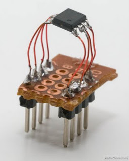 |
| All connections soldered and tested |
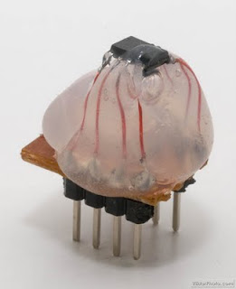 |
| Hot glue holds the assembly together – no going back from here! |
Like this:
Like Loading...
Related


wow! that's a great thinking, but is there a way where a normal part can accommodate in a SMD board.
I wanted to know as because i have a small radio and it has a chip IC in it. I am not getting the IC, but i can find the bigger version. It has about 30 pins in total and wanted to know if there are any solutions.
@D.D.Raikut: I haven't done that yet, but I would choose a similar approach, especially if it is for a permanent solution: connect the SMD pads on the board with the IC pins with solder small bits of wires. You can put the IC in a socket or on a small piece of (test)board if you like, but if it's to stay and you are certain it is the right replacement you can skip the extra bits and solder the wires directly to the IC pins. Then you can keep the whole thing in place with our good old friend, the hot glue. If you make it, don't forget to share your findings and a pic of it here!
Hi,
This is an incredible blog post. Absolutely love your work and would like to talk to you more. I've had a browse and cannot see to locate your email. Is there an email I can grab you on? Mine is rgibson(a)farnell(dot)com
I also found a similar solution but I'm a little worried about working with larger chips 50 pins and more.
@Anonymous: I haven't tried this, but I don't see why it should be more difficult. You can tilt the chip on its side and use some sticky tape to keep the small pieces of wires organized while soldering the rest…