Introduction
In the previous article I described the system overview of my automation platform, which I call ActoSenso Platform. In this article I discuss some of the nodes that can be (and I have) used in ActoSenso Platform. Any suggestion, tip for improvement, constructive criticism or related comment is mostly welcome in the comments area.

What is an ActoSenso Node?
ActoSenso Nodes are small hardware devices that are the “eyes”, “ears” and “hands” of the ActoSenso Platform. They are the interface between the real physical world and the computer that ultimately does the home automation.

ActoSenso Nodes are normally designed for a particular simple task (like switch on or off something when the server so instructs it), but it is possible to create more complex ActoSenso Nodes as well, that perform complex calculations and/or operations. It is also possible to make an ActoSenso Node so powerful that no ActoSenso Server is needed. Of course, in this case some features (of an ActoSenso Server) will not be available, because of the hardware limitations of the chips used ActoSenso Nodes. Later, I will show some examples of ActoSenso Nodes for standalone operation as well as networked operation.
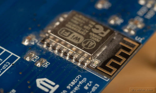
Example node (PCB): Temperature and Hall sensors:
It manages 5 Hall sensors and at least 4 DS1820 family temperature sensors.
Why ActoSenso Nodes?
The following properties of the ActoSenso Nodes make them ideal for a typical home or business deployment:
ActoSenso Nodes
- are small, so they can be easily hidden.
- communicate with the server, the internet or each other via your existing WiFi connection.
- operate on a single 5V DC power supply, which any recent mobile phone charger can supply.
- can be shared across automation project. I.e. one ActoSenso Node can send its sensor data to multiple ActoSenso Servers.
- are cheap, so even multiple nodes that do the same thing can be deployed at small extra cost to get more reliable and accurate sensor data.
- can be updated without temporarily removing them from their location and connecting them to a computer. OTA (over-the-air update) is possible and is the recommended way to update ActoSenso Nodes. OTA is fast, reliable and eliminates a lot of hassle.
Anatomy of an ActoSenso Node
As the basis of an ActoSenso Node I chose Espressif‘s ESP8266EX chip. This is purely my preference at this time. Other ActoSenso Nodes can be developed based on other chips, as the communication between ActoSenso Nodes and ActoSenso Servers are open standards so 3rd party developers can create new nodes. In this article, though, I will focus on ActoSenso Nodes I have created already. These ActoSenso Nodes are all based on the ESP8266 chip.
As a minimum, each ActoSenso Node contains an ESP8266 based module from Ai-Thinker. This module handles all WiFi communications and still has some more oomph to handle a variety of other functions, like GPIOs, timers, etc. I use the ESP-12E and ESP-12F variants the most, mainly for the following reasons:
- They are (almost) pin compatible.
- They are both FCC approved, so they are suitable for commercial applications.
A minimalist ActoSenso Node would also have at least one sensory input (digital or analog) or an actuator output. The upper limit is your imagination. Although the number of IO lines of the ESP module is limited (about 8) these can be easily extended by using I2C, SPI or SIPO (serial-in parallel-out) or PISO (parallel-in serial out) port extenders. Later I will show examples for this as well.
Since the ESP8266 operates on 3.3V DC an LDO (low dropout) power regulator is on-board to provide up to 1.5A current to the ActoSenso Node.
Also, depending on the ActoSenso Node a number of LEDs can be used to show status information.

Firmware outline
I have already created a few ActoSenso Nodes – some have some sensors, some have actuators, some have both. Below I gather those parts of the firmware that make up the “core” of the firmware. These bits are common to each ActoSenso Node.
- WiFi connection management: This is kind of obvious. At power up, the ActoSenso Node tries to connect to the previously connected wireless network. If it succeeds, great! If it doesn’t (WiFi network not available temporarily, or first time power up) it creates a WiFi network of its own. This allows the user to connect to it with a smart phone or computer and set it up. One of the settings allows to select which available wireless network the ActoSenso Node should connect to.
- OTA: In most cases I view over-the-air updates an essential part of the firmware. It allows updating/replacing the firmware remotely, without physically being close (or connected) to the ActoSenso Node. This saves a lot of time and effort on the long run. Only the initial programming must be done through a serial programmer, any subsequent updates can be sent to the device remotely, even through the internet.
- Web server: A small web server is also included in the firmware. The reason is that initial configuration has to be done somehow, and I don’t like hard-coding connection info (user names, WiFi details, passwords, etc) in the source code. Also, most functions of a ActoSenso Node can be accessed through its web interface. I will show some examples later.
- MQTT publisher/subscriber service: This allows the ActoSenso Node to communicate with the ActoSenso Server.
- Event logging system: Although this item is low on this list, this is as important as any of the preceding ones. You may not use it on a regular basis, but when there is a problem in the system it makes troubleshooting much easier. The event logging system is built on MQTT.
- Serial debug information: Debug information is constantly pumped out on a serial port (115200, 8N1) to aid development. This can be switched off in a production environment.
The rest of the firmware is device/application specific. I will discuss some of the more interesting bits at the specific examples.


