
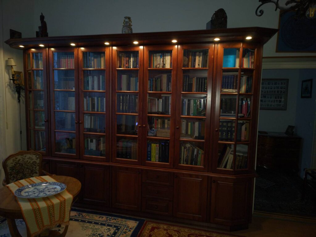
Pulse-width modulation (PWM) is a powerful technique for controlling power delivery to devices like LEDs, motors, and heaters. In this project, I built a 4-channel PWM controller/driver using an ESP32 (for smart control), the TC4427 MOSFET driver (for robust gate driving), and the CSD17573Q5B MOSFET (for efficient power switching). This setup is perfect for applications requiring precise, adjustable power control with minimal heat dissipation. My specific application is a spotlight controller for a friend of mine. His spotlight consists of 8 12V LED bulbs (built into a bookshelf) that consume about 1.25A total.
The device I created has the following key features:
- 4 independently controlled channels (my friend is using only 1 of them)
- Remote control: Currently, control through MQTT messages (WiFi) is implemented, but it is possible to expand functionality via Bluetooth with a simple firmware upgrade.
- High efficiency: The CSD17573Q5B’s low RDS(on) greatly reduces heat generation.
- Independent: Although it is recommended to connect the device to an existing home/business WiFi network, it also works stand-alone.
- Wide range of applications: It can drive any analog load up to 18V and 10A (combined). This current can be further raised with adequate heat sinks on the MOSFETs as well as strengthened PCB tracks. Possible applications include DC motor control, (LED) light dimming, heating/cooling element regulation, and many more…., even custom lab supplies!
- Privacy respecting: The device doesn’t collect/track any user activity. The built in telemetry messages are for the user’s own information, only sent to the user’s own MQTT server, and even this only happens if the user sets up MQTT. The device works happily without an MQTT server.
- Can be easily integrated into any smart home. As such, it can be part of bigger automation rules. E.g. you can set it up to increase the lights as the sun is setting…
- Easy, over-the-air (OTA) updates
- Fully open source: all sources are open to the public, including the CAD files required to print an enclosure for the PCB.
Hardware
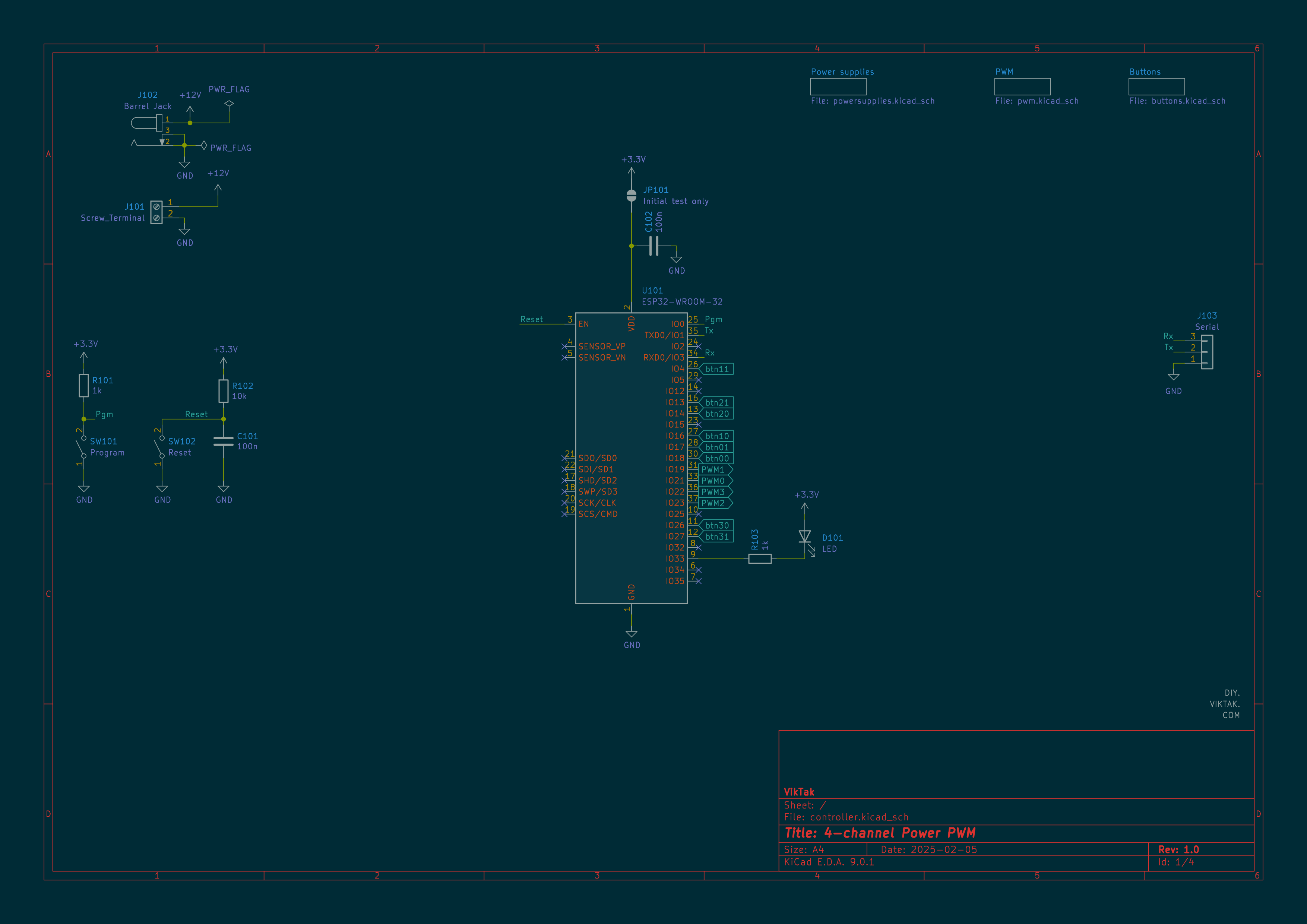
The brain of the operation is an ESP32-WROOM-32. It provides the PWM signal for the driver circuit and performs all the “iot” functions so that the circuit can be controlled remotely, even as part of a smart home or industrial installation. In this application, I use four channels configured with the LEDC (LED Control) peripheral. The PWM hardware in the ESP32 supports high-resolution PWM (up to 16-bit), but I only use 8 bit resolution which is plenty for my purposes.
Driving the LEDs are four power MOSFETs, one per channel. I chose the CSD17573Q5B n-channel MOSFET because it has a very small on-resistance and is readily available in tiny packages. The CSD17573Q5B has a drain-to-source on-resistance of 0.84mΩ @ 10V. This parameter must be as small as possible in a circuit like this, because when the load is driven at full power, all the current flows through the MOSFET. For example, if there is a 10A load the power loss on the MOSFET can be calculated like this: P=I2*RDS(on)=100*0.84mΩ=84mW=0.084W. In my application, the load takes about 1.25A, which means losses of around 0.13mW. The MOSFET is capable of driving 100A continuously (with proper cooling), but the PCB I designed should not be abused with loads greater than 10A total. In the final circuit, the MOSFETs are enclosed in a 3D-printed enclosure with no active cooling. After several minutes of full load, I still can barely notice the increased temperature of the MOSFETs by hand.
There is a catch though with the CSD17573Q5B MOSFETs: In order for them to have that low resistance they have to be driven with higher voltages than the ESP32 is able to. The ESP32 can generate a 0-3.3V PWM signal, but this is not enough to switch on the MOSFETs fully. According to the datasheet, 3.3V might just be enough for the CSD17573Q5B to start conducting, but for low resistance conductivity much higher voltages are required:
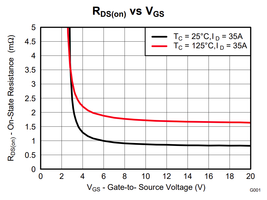
To achieve a lower on-resistance, I needed a driver for the CSD17573Q5B. I decided to use a dedicated MOSFET driver chip. I could have opted for a simple transistor/resistor combo. However, I wanted to try something I hadn’t done before. After some research, I settled on the TC4427. The TC4427 acts as a buffer between the ESP32 and the MOSFET: The ESP32 generates 0-3.3V PWM, which the TC4427 boosts to drive the MOSFET efficiently. A single TC4427 can control 2 MOSFETs. Any member of the TC4426/TC4427/TC4428 family can be used in my circuit – they only differ in output drivers: the TC4426 has two inverting drivers, while the TC4427 has two non-inverting drivers. The TC4428 has one inverting and one non-inverting driver. My code is for the TC4427, but it is really easy to adjust it for the others.
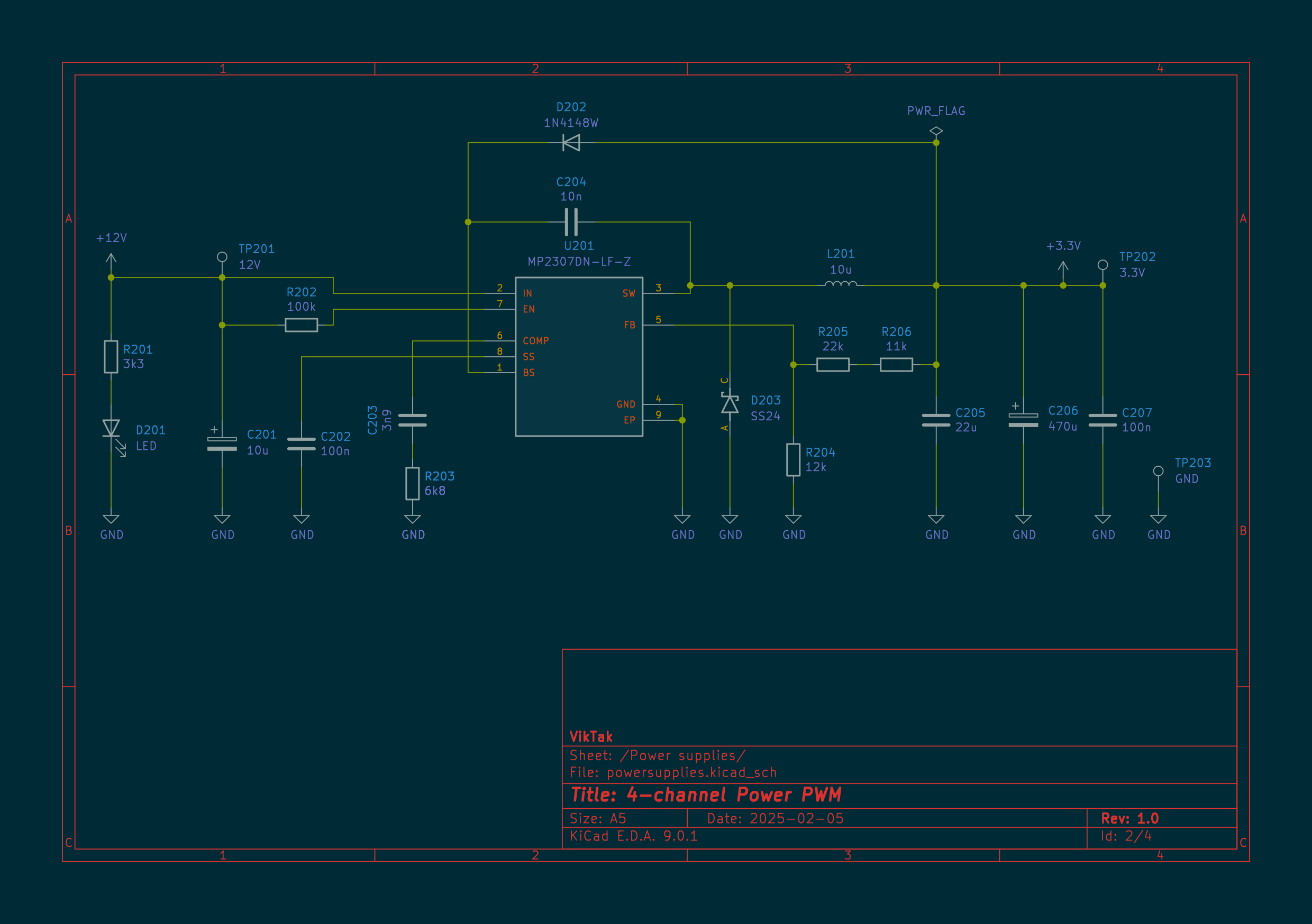
To power the logic part of the circuit I use a standard 3.3V switch mode power supply – in the same configuration as I used it before in other projects.
Finally, there are a couple of push buttons per channel to get user input on the device. This enables the user to control the circuit locally. In my application the buttons are used to increase/decrease the luminosity of the spotlight.
The circuit is built using mostly SMD components. This allows for smaller size of the PCB and a smaller final “product”.
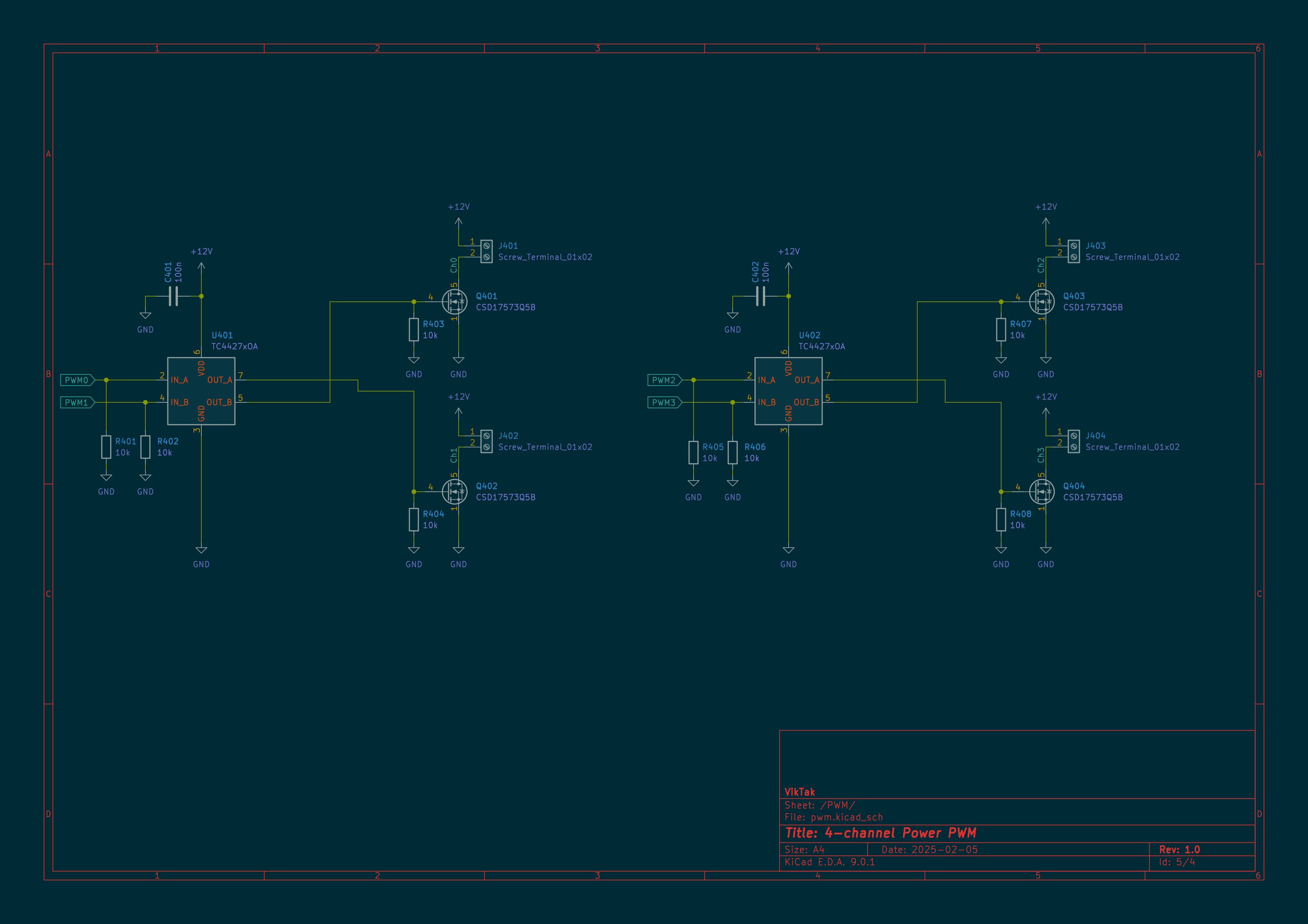
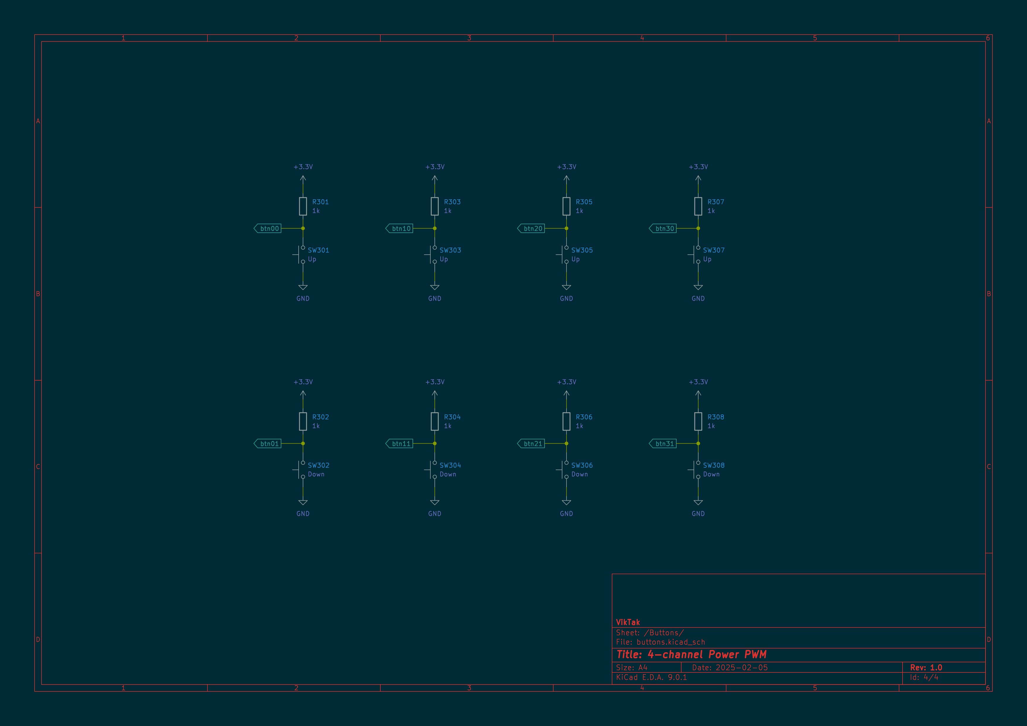
Here is the complete schematics for the project:
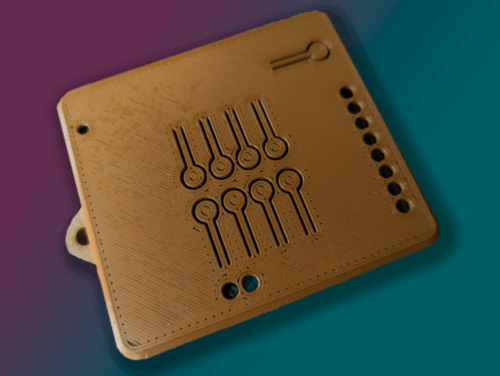
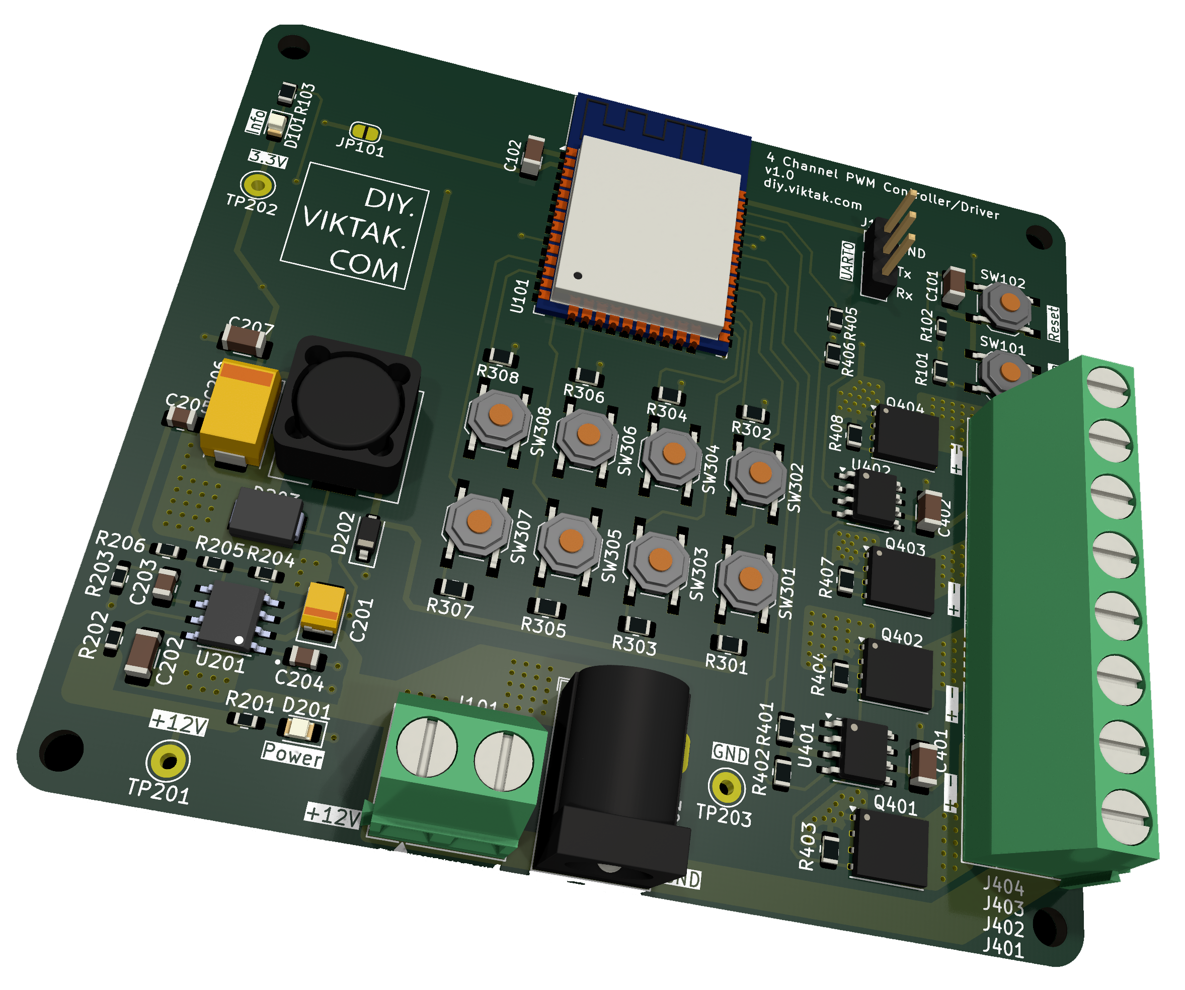
Here is a 3D render of the circuit as well as a picture of the actual, fully assembled unit:
A huge thank you to PCBWay for sponsoring this project! Their high-quality, affordable PCB fabrication made it possible to bring this 4-channel PWM controller to life. PCBWay delivers excellent manufacturing standards with ultra-competitive pricing, fast turnaround times (as quick as 24 hours for prototypes!), and reliable shipping worldwide. Whether you need 2-layer boards or advanced multilayer designs, their service is consistently precise, cost-effective, and professional.
Want to build your own? You can order this exact PCB from PCBWay by clicking on the image on the right!
For makers and engineers alike, PCBWay is a fantastic partner for turning circuit designs into reality—check them out for your next build!

Firmware
The firmware is written using the Arduino framework for the ESP32. I recycled the basic functionality of the firmware from my earlier projects. These include:
- WiFi connection management: At system start the device tries to connect to the last used access point. If it can’t, it creates an access point of its own.
- Device settings can be controlled via its built in web server.
- OTA updates via WiFi
- Connection to an MQTT server for telemetry and remote control of the device
- Heartbeat messages through MQTT at predefined intervals
Settings specific to my particular application:
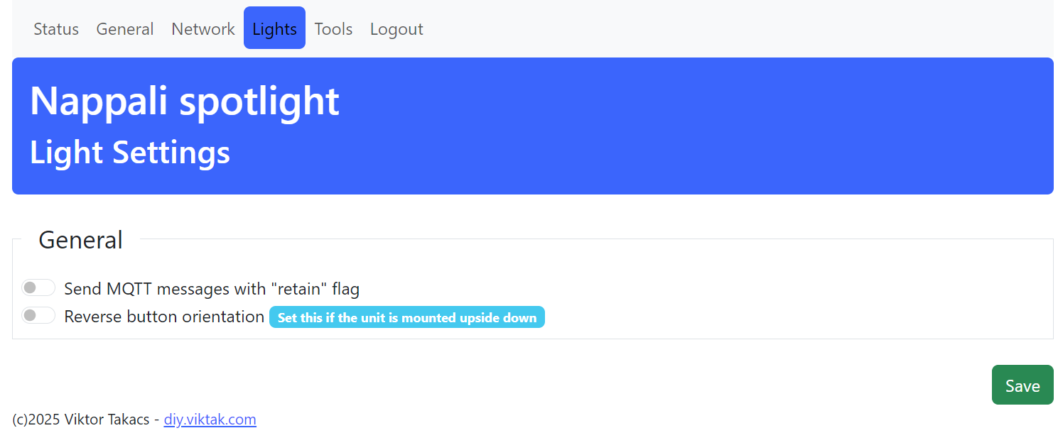
- Ability to invert the buttons: if the device is installed upside down (for space limitations), the button functions can be swapped with a single setting.
Some of the functions for controlling lights currently implemented:
- ButtonClick event: The light in the channel belonging to the button used dims one notch up/down.
- ButtonDoubleClick event: The light in the channel belonging to the button used is set to full/no power.
- ButtonLongClick event: All the lights are set to full/no power.
- All channels can be remotely controlled with MQTT commands. If, for example, a command is sent using the
retainflag, the same dimming will be set after a system reboot.
It is worth mentioning that, since the human eye does not perceive changes in brightness linearly, a so called gamma correction is needed to adjust the intensity of LED light so that they are perceived more uniformly by the human eye. This adjustment is necessary because the eye is more sensitive to lower levels of light, meaning that small changes in brightness at lower intensities are more noticeable than similar changes at higher intensities. To correct for this I use a gamma-correction lookup table. I got the right values from experimenting a bit with this Gamma lookup table generator.
All the source code is available in the project’s public repository.
Enclosure
I created a simple enclosure for this project. I finally got to use version 1.0 of FreeCAD that had been released just a few weeks before my circuit was finished:
The box is printed as two separate parts – top and bottom. No special settings or supports required to print either part. The STL files can also be found in the project’s repository, in the CAD directory.
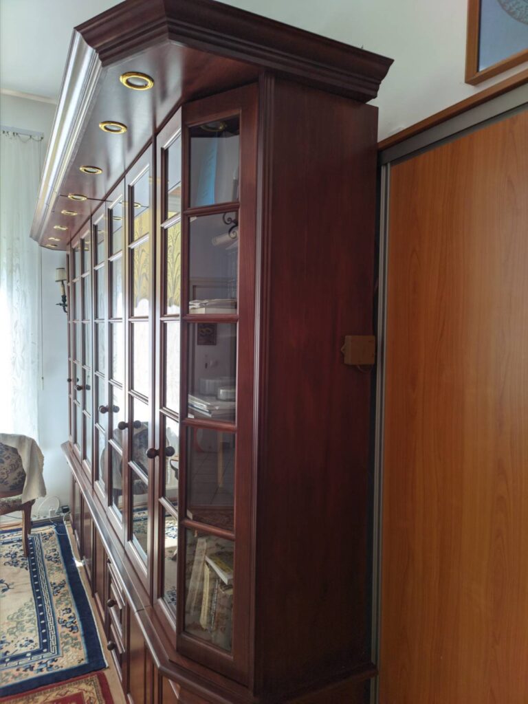
Here is the final box mounted on the side of the bookshelf:
Final Thoughts
This 4-channel PWM controller/driver combines the ESP32’s programmability with robust MOSFET driving and switching. The TC4427 ensures clean gate signals, while the CSD17573Q5B handles high currents efficiently. With minor tweaks, this circuit can be adapted for various power control tasks—perfect for DIY automation projects!
