 |
| Finished unit mounted on the wall, in use. |
Introduction
This project, like others before, has started out of need: our 30+ year old mechanical timer for the central heater of the house has finally given it up. It would have been faster and cheaper to get a replacement from the local hardware store, but I decided to learn something new and I set out to create a digital version of it.
I wanted to create something simple, something that anybody can use without any experience in electronics – i.e. not a geeky device that could only be used by me, but something that anyone living in the building could set up properly, given a User’s manual.
I did a quick research asking people in the building (mostly relatives) about what functions they would like to see in the new timer. As much as I wanted to cram as many features in the device as I possibly could I had to leave most of my ideas for another project – the consensus was to be able to set up periods of time (from now on: time slots) within a day when the heating is on. Period.
However, with some modifications in the firmware new features, like time slots set up for any day of the week or month, could be easily added.
With minor modifications of the hardware this could be extended to several channels, i.e. more than one “item” could be programmed to be switched on/off in a given time slot.
This timer is currently used as a timer switch for the central heating of the house, but it can switch pretty much anything you attach to it. I will still refer to the output as heater for the rest of the article.
As usual, this project is available as kits or fully built units – for details, please drop me a line.
Hardware
I based the circuit around a Microchip PIC18F4550 microcontroller, because I had been experimenting with them for a while and want to learn them. I have both TTH and SMT versions of the chip, so I can use one for prototyping and the other for the final PCB.
Timekeeping is done by a Maxim/Dallas DS1307 real time clock chip which communicates with the micro controller using I2C. Operation is backed up with a battery so that after a power break time is not lost.
The user interface is nothing fancy – it consists of a 16*2 LCD and 6 momentary switches (pushbuttons). Using the buttons the device can be configured and the LCD display provides feedback. An LED is also used – it shows if the heater is currently on. This is needed, because the layout of the house is such that the heater is far away from this control device, so there is no visual/audio feedback for the user to know if the heater is on or off.
 |
| The circuit is very simple, made up of only a handful of blocks. |
The heater is switched on and off using a small 12V relay. There are no high currents to switch, so using a small, PCB mounted relay makes the device compact.
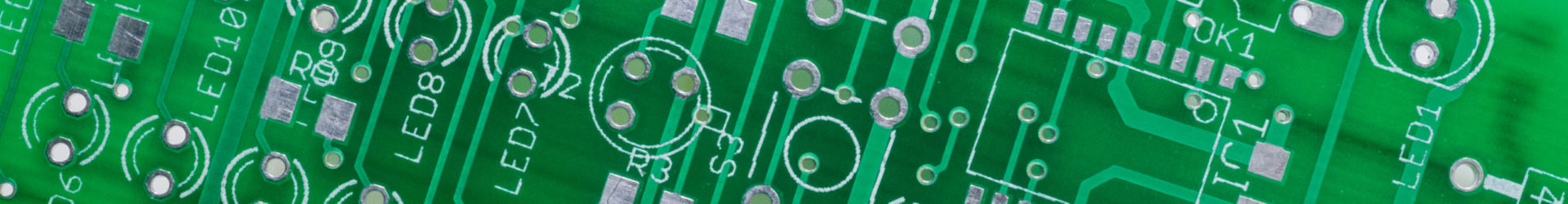
 |
| Front side of PCB. PCB size is about 100mm * 75mm. |
 |
| Back side of PCB. |
The unit is powered with a common 12VDC wall adapter.
Firmware
One of the reasons for using a 18F4550 is that I wanted to start learning C programming on PIC microcontrollers. I found this PIC to be ideal for learning C on PICs as it is optimized for C, has plenty of program memory and it has a wealth of supporting material on the internet.
Timeslot settings are saved in the PIC’s EEPROM, so after a power break the settings are intact.
The firmware is written in C18, compiled with the free version of Microchip’s C18 (v3.41) compiler.
To get a copy of the firmware, please drop me a line.
Layout/Build
I used SMT parts for most of the parts to keep PCB size minimal. The final PCB size is 10cm * 7.5cm (4″*3″). The PCB is not very densely populated, because there are a few relatively large parts that dictated a sort of “comfortable” size.
The LCD is the most demanding part: it’s big and it should also be placed in a location where it looks good. I decided to put it in the centre, slightly towards the top. I placed the buttons on the side – 3 on either side of the LCD. The LED (that shows if the heater is on) is placed under the right hand side buttons.
The 12VDC connector is in the lower left area of the PCB while the switched output of the relay is placed in the lower right corner to be far away from anything else on the PCB. I used SMK sockets as switched output connectors.
Concept/Operation
-
An “always on” function can be set up by creating a time slot 00:00->23:59.
-
An “always off” function can be set up by deactivating all the time slots.
-
Overlapping time slots can also be set up.
-
By activating/deactivating specific time slots we can accommodate a wide range of heating policies for different kinds of cold days in the winter.
Set up
 |
| This is the default screen. |
 |
| Menu item #1. |
 |
| Menu item #2. |
 |
| Menu item #3. |
Once the desired menu is selected the values can be changed by the Up/Down buttons. When there are multiple values to be changed (i.e. hours and minutes), the Right button loops through them.
The user can accept and store the new values using the Enter button or abort changes using the Cancel button.
 |
| Whenever new values are stored this confirmation is displayed as user feedback. |
In any menu, if there is no button pressed for a few seconds the menu is aborted and the screen returns to displaying date and time.
The Boost button can be used any time to start the heater for 60 minutes. This is independent of any timeslot setting. Pressing the Boost button while it is already in boost mode will switch it off.
 |
| Pressing the boost button causes the timer to switch on immediately for 60 minutes. |
 |
| Pressing it again ends the “boost period” immediately. |
To illustrate usage I took a few “screenshots” of the different modes (WOW, on these close-ups you can really see the dust settled on the prototype!):
 |
| The flashing underscore means that the Up and Down arrows have effect on this element. |
 |
| Setting time. |
 |
| A timeslot is about to be edited |
 |
| The “*” symbol means that this timeslot is active. When entering edit mode, this is the default item to change, for ease of use. |


License

This project is licensed under a Creative Commons Attribution-NonCommercial-ShareAlike 3.0 Unported License.

Definitely reminds me of my project: http://tinkeringetc.blogspot.com/2012/08/automatic-garden-waterer-part-2.html
although more polished. Looks good, good work!
Very nice! I especially like the printed box – I wish I had a printer too!
hy may i download or copy hex file ,,, thank
Leave you e-mail address here, or send it to me and I'll send the code to you.
hy may i download or copy the code file ^.^ thank very much
quychienvodich@gmail.com
I like this project and i hope to made my own 🙂
May u can send me the firmware plz
My email : badranyasser@yahoo.com
Code sent in private mail.
Code sent in private mail.
Thanx a lot 🙂
Please share the code to me at kapildhyani88@gmail.com
Code sent in private mail.
Code sent in private mail.
Please share the code to me at sherinp.shaji9@gmail.com
Code sent in private mail.
I hope you can send me the code and schematic at qyaiba@yahoo.com.my . It is very interesting project…
Code sent in private mail.
please send the code to renjithgv@gmail.com
Code sent in private mail.
This comment has been removed by the author.
sweet!
can i ask for the code??
mmm. . tnx in advance. . ^_^
>>ragacheenee@gmail.com<<
Code sent in private mail.
I like this project and i have to made my own for use in my farm
Please send code to >nineole@gmail.com<
Thank you so much.
hi, i like your project. Please send me firmware code/hex file at : jasim.shah@outlook.com
Code sent in private mail.
Code sent in private mail.
Thanks! for code. Can you please send me compiled Hex file?
On its way!
hi can i have a code of this? Djdaniel_teo@hotmail.com
Code sent in private mail.
Kindly send me the code to my mail id.
everguru@gmail.com
Code sent in private mail.
senthil
i like this project can u send code my mail id is nsen2k@gmail.com
Code sent in private mail.
hi! have been working on a similar build, any chance you could share you code to help me learn? onsan63@gmail.com
thanks Viktor.
Paul.
Code sent in private mail.
hi victor… i like your project… can you share your code..
is that the code in C languange?
Q_diphenhydramine@yahoo.com
thanks
Code sent in private mail.
Hi Viktor,
Very nice timer indeed!
Can you please sent me the code and the hex file so that I can try my hands on it?
My email : mikelow1957@gmail.com
Thanks in advance.
Hi Viktor,
Very nice timer indeed!
Can you please sent me the code and the hex file so that I can try my hands on it?
My email : mikelow1957@gmail.com
Thanks in advance.
Code sent in private mail.
Hi Viktor,
Nice project and also very usefull for me.
can you please send me source code with hex file.
Its a tuf job to make it on general purpose board.
So can you mail me pdf of pcb which will be very helpfull.
Thanks & Regards,
Nikhil
My email ID: nikhilpnp@yahoo.com
Code sent in private mail.
Code sent in private mail.
Hi Viktor,
May u can send me the code plz
My email : tircispb@gmail.com
Thanks in advance.
Code sent in private mail
hi Viktor
i am brazilian and i liked your project can you send me source code with .hex file?
thanks my e mail is douglasperuzzo@hotmail.com
sorry my english is bad.
Code sent in private mail.
hi Viktor,
awesome project. i sure would want to build one right now to control my air conditioner. it would greatly help if you can send me the firmware code/hex file at levian13@yahoo.com
thanks and regards,
levian
Code sent in private mail.
Hi Viktor,
Nice project and also very useful for me.
I'm professor in gymnasium (Bihac – Bosna and Herzegovina) and this project
is very useful in my laboratory.
Thanks in advance.
Hi Viktor !
Nice project. Can you please email me the source codes file at : jahanzebgul89@gmail.com
Code sent in private mail.
Hi I'm Róbens i would like send me your source code and .Hex file i'm working a project with PIC18F4550.
And your source code is very good.
Sorry my english is bad.
Email:robensferreira@gmail.com
Code sent in private mail.
Olá! bacana o projeto, poderia me enviar o código fonte?
Obrigado!
E-mail: marcioleandrobp@gmail.com
Code sent in private e-mail.
Hello, I really like your project and I want to do it too 🙂 . Can you share the codes with me?
Just did it! 🙂
Have fun!
Pingback: Smart Timer Upgrade – Viktor’s DIY Blog