For years this basic timer has worked very well in our house controlling the central heating. It was a success among all people because it was easy to set up and after the initial configuration we haven’t really touched it for years. It just kept working without getting in our way.
After several years, I thought it was time to bring this dumb timer to the modern ages: I wanted to upgrade it so that it became a full member of out home automation system. I decided on the following simple set of requirements:
- It should retain all the good features of the previous timer, i.e. setup-and-forget.
- It should be configured via Wi-Fi, so I can eliminate the need for a display on the device. This allows the device to be smaller, less complicated and cheaper.
- It should show up in Home Assistant (show its status, be controlled..)
- Should retain the “Boost” functionality on the device itself.
- Should be drop-in compatible with the previous one, so that I don’t need new cables, etc.
Hardware
Since I have plenty of ESP8266 modules at home and this project doesn’t require much processing power, I decided to build the timer circuit around an ESP-12F module.
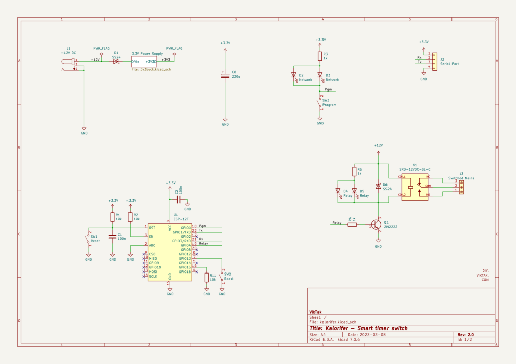
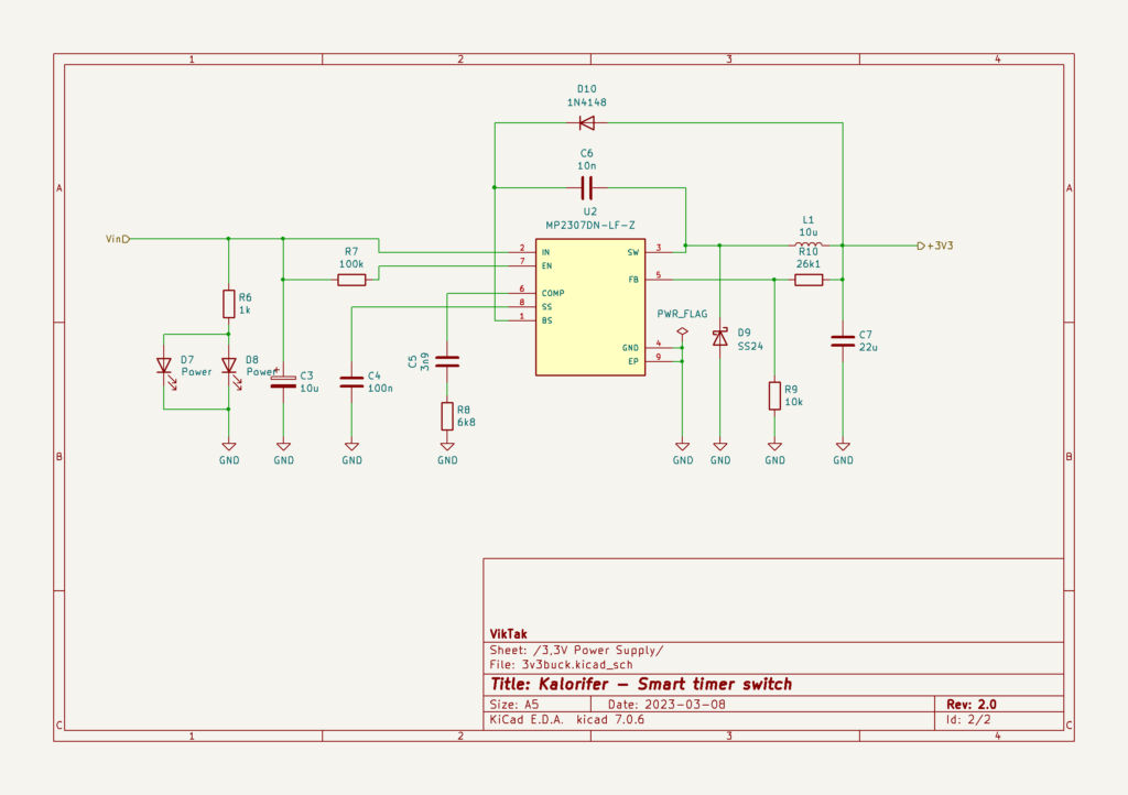
The circuit is relatively simple, and I used this opportunity to create my first circuit that uses a custom buck converter. Using a linear voltage converter wouldn’t make sense here as the ESP needs 3.3V and a linear converter would waste too much electricity as heat, which would have needed a relatively large heatsink. As the switching IC I used the MP2307 synchronous rectified step down converter, which is also used in many of the cheap variable buck modules available in online stores. It only requires a handful of external components to operate, it is efficient and runs cool.
Using a barrel socket for power was chosen to eliminate the need of replacing the power wire that is already mounted on the wall. The relay which switches the central heater on operates from the 12V directly and can switch loads of up to 10A @ 220V. It is driven by a generic NPN transistor.
The BOM is available in the project’s repo.
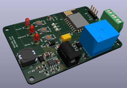
Here is a 3D render of the board:

Sponsored PCBs
At this point I would like to thank PCBWay for sponsoring this project: Although it would be possible to make this PCB at home, I opted for a professionally made one by PCBWay. I have used them in the past with success and I knew that the PCBs I order would turn out great. The ordering process was smooth, and within 24 hours of ordering, the finished PCBs were handed over to the post. The PCBs arrived in perfect condition, with plenty of protection around them. The soldering pads were all clean and soldering was a breeze, no cleaning of the PCBs first was necessary. I also found out to my surprise, that even though I ordered 10 PCBs, I got 11 in the box. Awesome! If you also want your own light controller PCB professionally manufactured, click on the picture to the right and order your PCBs today!

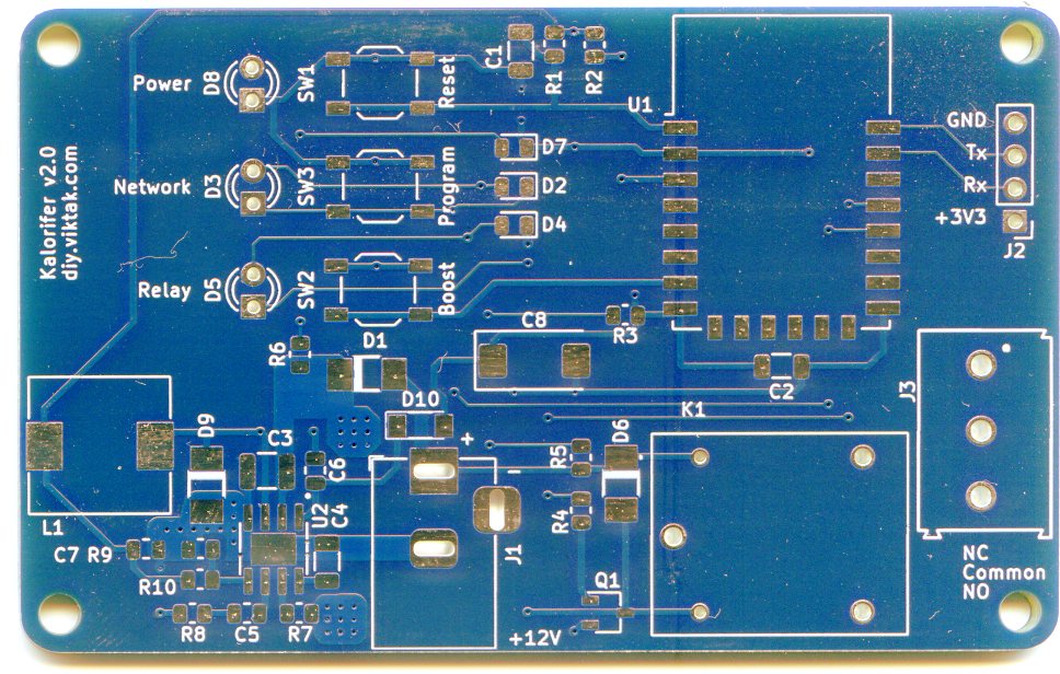
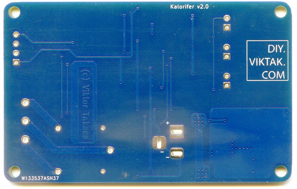
This this is how the PCBs turned out:
Firmware
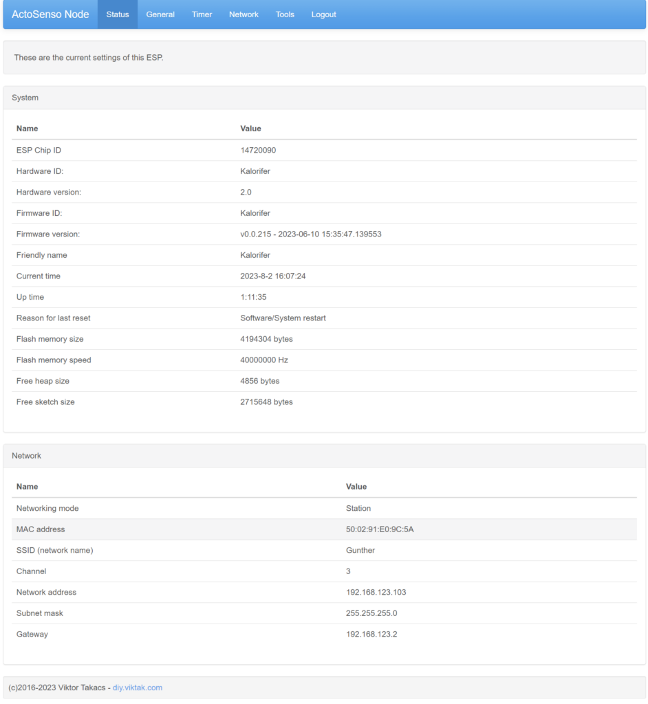
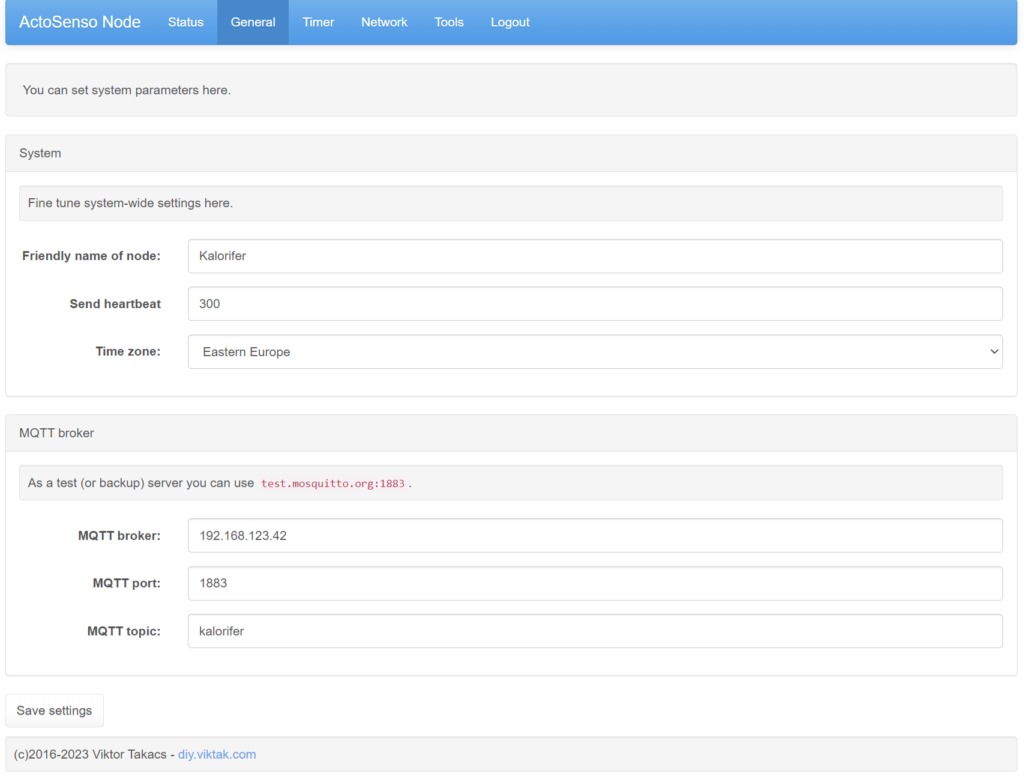
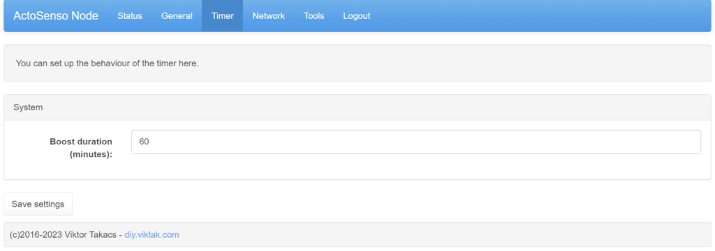
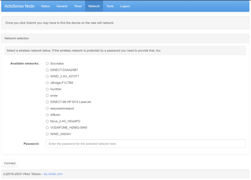
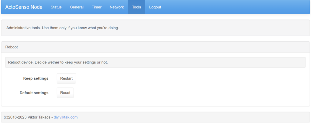
First I reused as much of my own skeleton code for the ESP8266 that I have used in so many previous projects as possible. Then I extended the code to handle the functions specific to this device. The result is that with little effort I have a new device that behaves similarly to all my previous projects. For example, here are a few screenshots of the web settings interface:
The source code is available here.
If you don’t like my code, feel free to contribute or make suggestions to improve on it, and if you want to use it with your own code, feel free to do so. Just let me know in the comments below, so that I can be proud! 😉 You can also Tasmotize it!
Integration with home automation projects
This little device can be used with any home automation platform as it uses MQTT to send and receive messages to and from any kind of controller. This is how it looks in Home Assistant, which my home automation is based on:
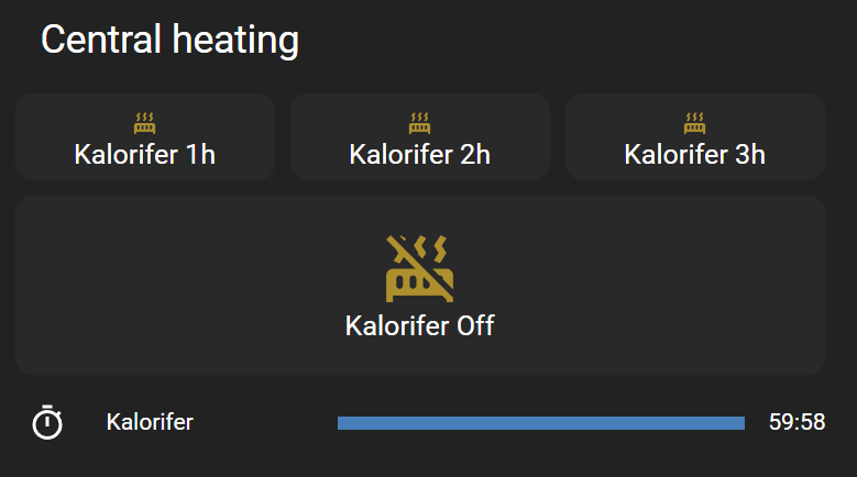
The top buttons can start the central heating for a period of 1/2/3 hours, then it will automatically switch off. The bottom button can also switch it off immediately. Pressing the Boost button on the device itself also starts the central heating for an hour. through Home Assistant one can create very complex rules for switching on the central heating as one wishes. The limit is your imagination!
Home Assistant is not the only automation platform this can work with. With minor modifications in the code this device can be a full member of any automation framework.
Of course this timer device is a generic device for switching on and off things. It doesn’t have to be a heater, it can be anything that normally runs on mains. Could be a lamp, washing machine, irrigation system, etc.
Enclosure
I also designed a basic enclosure for this timer device. All done with FreeCAD:
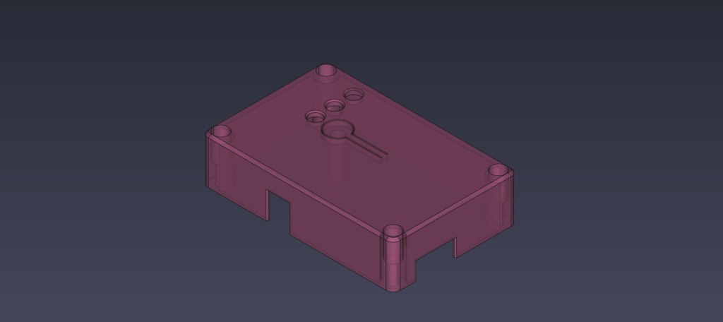
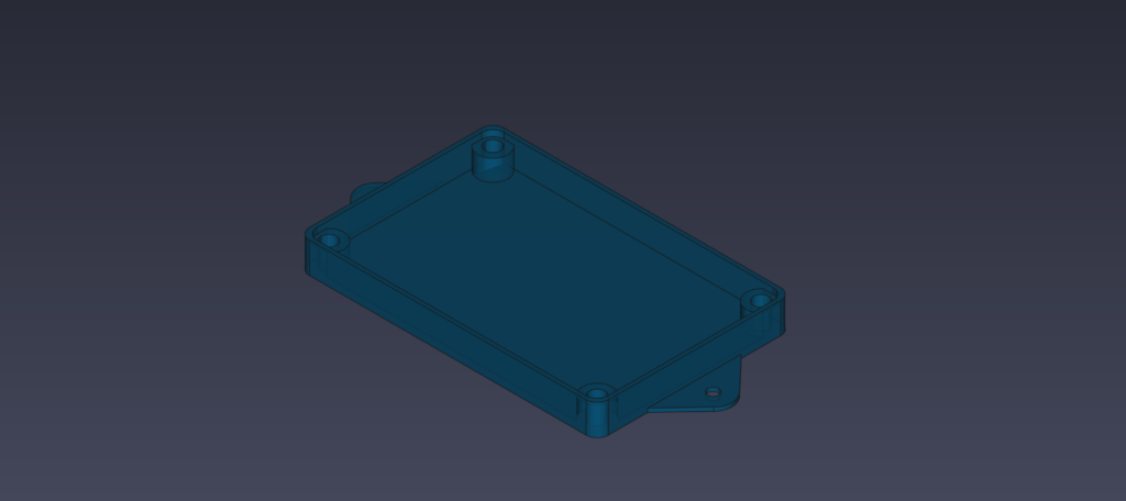
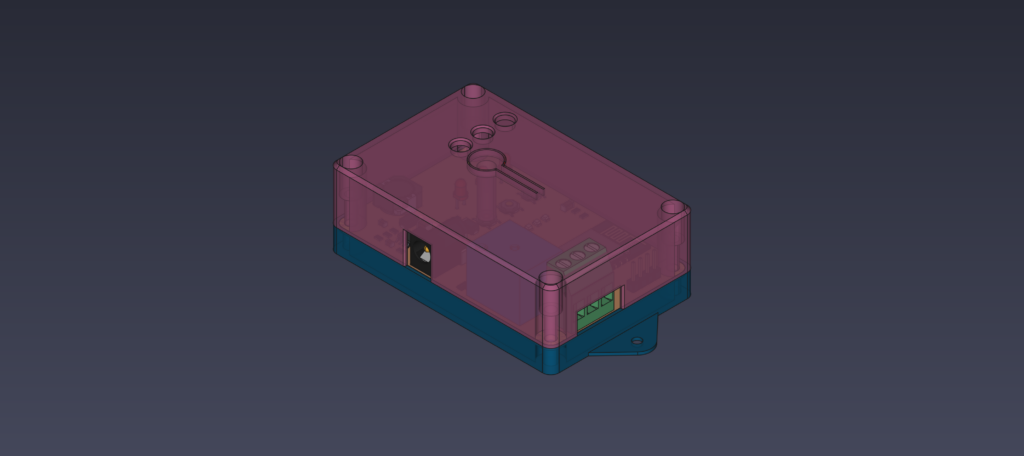
The top and bottom part are held together by screws in the corners (from the top) and brass inserts (mounted in the bottom). The STL files needed to print these parts are also found in the project’s repo.
Conclusion
The device I just described above accomplishes all of the goals I set at the beginning and is a good starting point to create a multi-channel timer. Both the circuit and the code is easily modifiable with minimal effort. And it is not very sore on the eye either…
