
Since I live in an area where sunshine is almost always abundant, it makes sense to harvest energy from the sun as much as possible. This includes making various sensors around the house, especially the ones that are outside, operate with solar energy. This is usually not a very difficult task: just add a small and cheap solar panel, a LiPo battery, and an equally small and cheap charger, and call it a day. This is the theory, and it works like this. BUT. (There is always a BUT…) The various sensors I already use and am planning on using around the house are tiny, ESP8266/ESP32 based devices with a relatively low power consumption. However, when one designs battery operated devices we always try to minimize power consumption to make any battery last longer or to reduce the battery size/capacity. After all, even here the sun sets in the evening…
One way to reduce power consumption is to put the sensor in a deep sleep mode when it is not doing anything essential. For example, if I want to measure the air temperature every minute or so, the device should not operate on a continuous basis. It is perfectly OK for it to “sleep” 99.99% of the time, and just wake up every minute, measure the temperature, send the data to the “server”, then go back to sleep. Here we can see that adjusting the frequency of measurements, i.e. how often a measurement is taken and sent to the server can also gain significant gains in power consumption. For example, taking the above example of measuring air temperature every minute, if I can live with getting readings from the sensor every other minute instead of every minute, the battery will instantly last (almost) twice as long.
The ESP family of microcontrollers can connect to other parts of the infrastructure via Bluetooth and Wi-Fi. Bluetooth in my case is not adequate, because its range is too small for the distances the sensors are around the house. Wi-Fi consumes a lot of power generally, but using ESP-Now it can be kept at a reasonable level. ESP-Now is:
A wireless communication protocol for quick responses and low-power control
Espressif
One limitation of using ESP-Now is that it is only compatible with other ESP devices, so only another ESP device can receive the data sent using this protocol. So I decided to create an ESP-Now – Wi-Fi bridge that will sit somewhere in the house, with the sole job of exchanging messages between sensors and the MQTT server.
Hardware
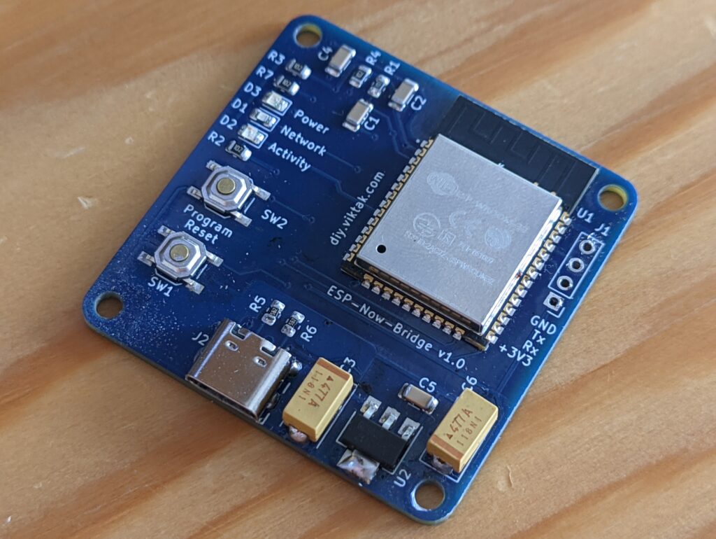
As expected an ESP32 is at the heart of the operations. The schematics is very simple, it only contains a few components apart from the ESP32, because all this board does is receives and transmits messages on Wi-Fi. For me this was an excellent opportunity to introduce a new way of powering the circuit with a USB-C connector. As I am running out of USB mini and micro connectors, I thought it was time to move forward and use USB-C from now on.
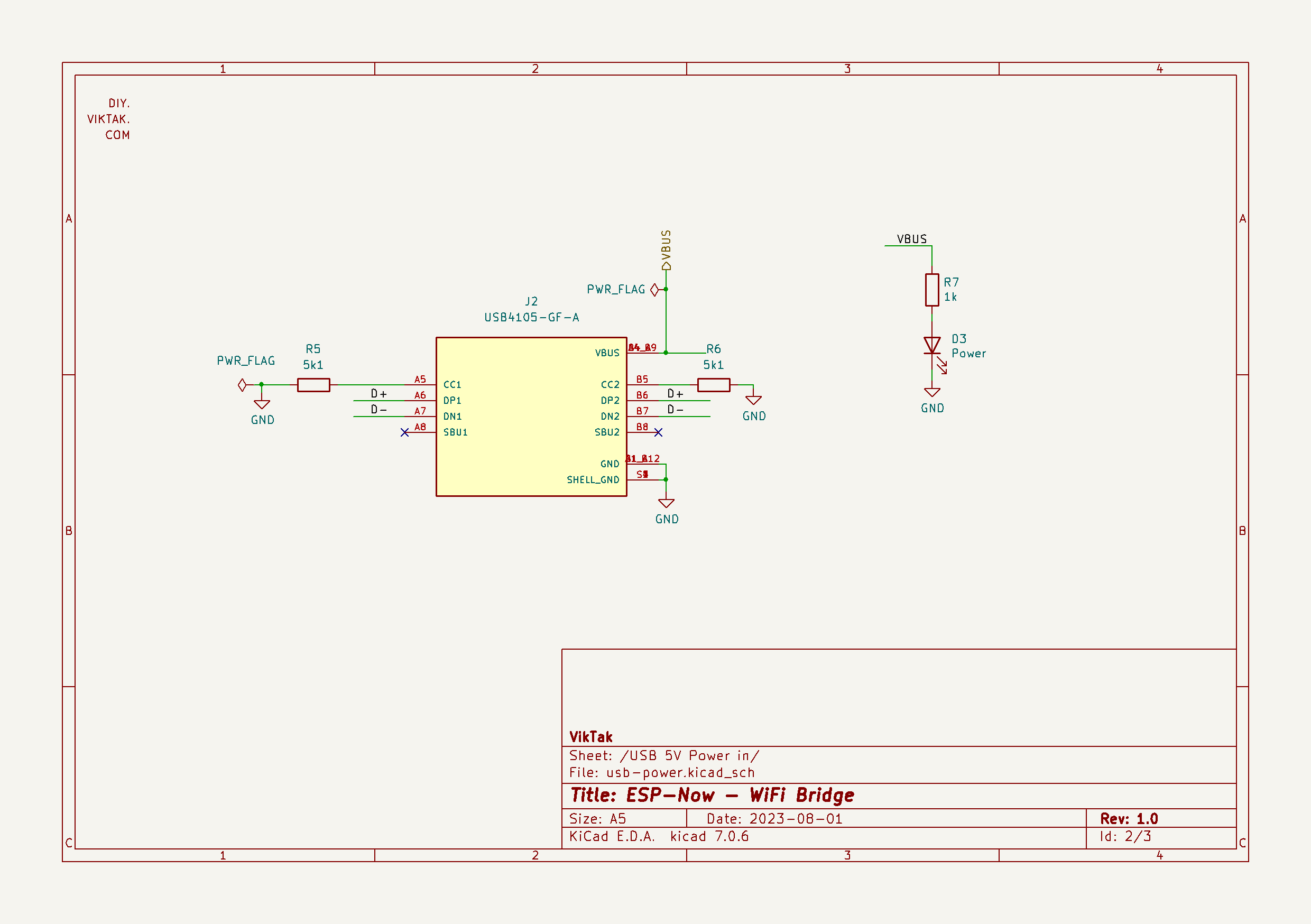
The USB-C standard makes it possible to power devices with voltages other than 5V (which is required by my design) using relatively complicated software negotiation via specialized ICs. Luckily, it is possible to get a traditional 5V out of any USB-C charger by using just two resistors. This way I didn’t need an extra chip and/or complicated programs to negotiate 5V:
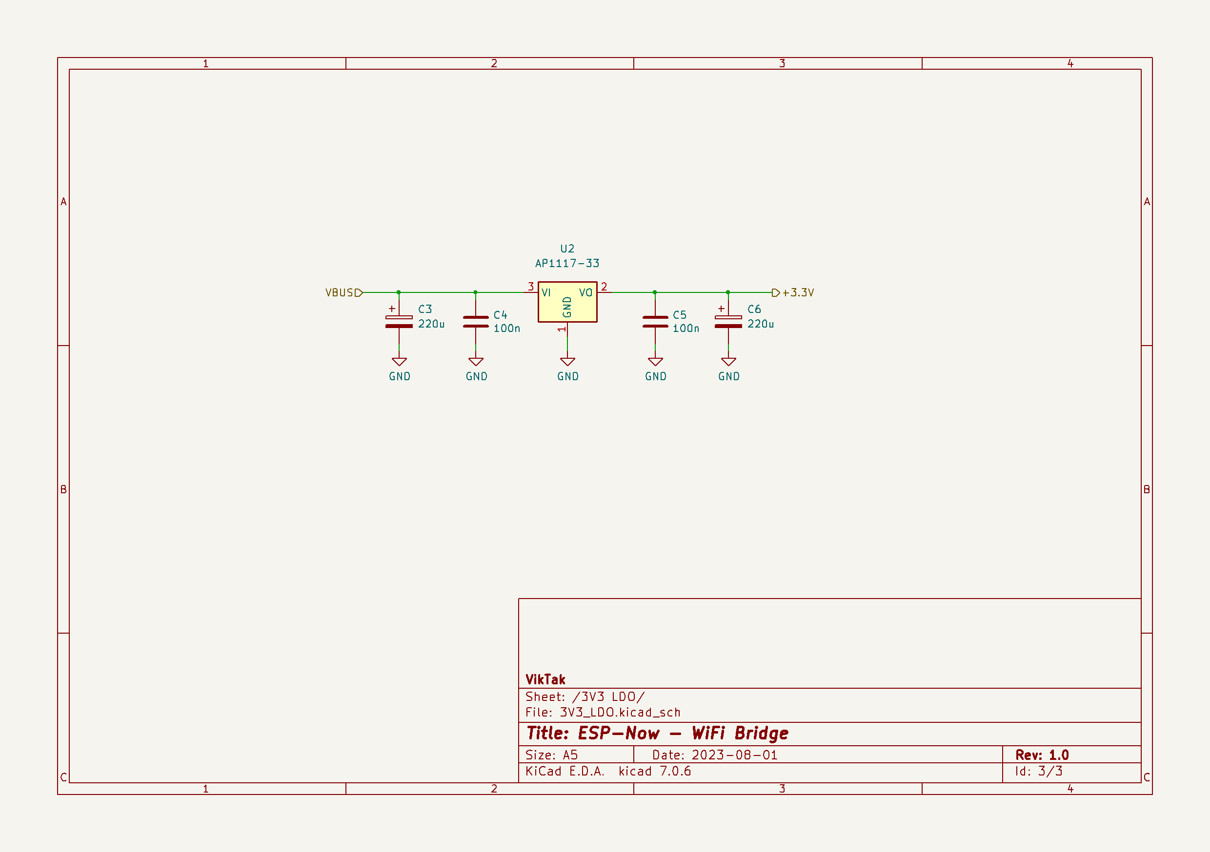
The ESP32 needs 3.3V, so the next step is to step down the 5V using an LDO:
Here is the rest of the schematics:
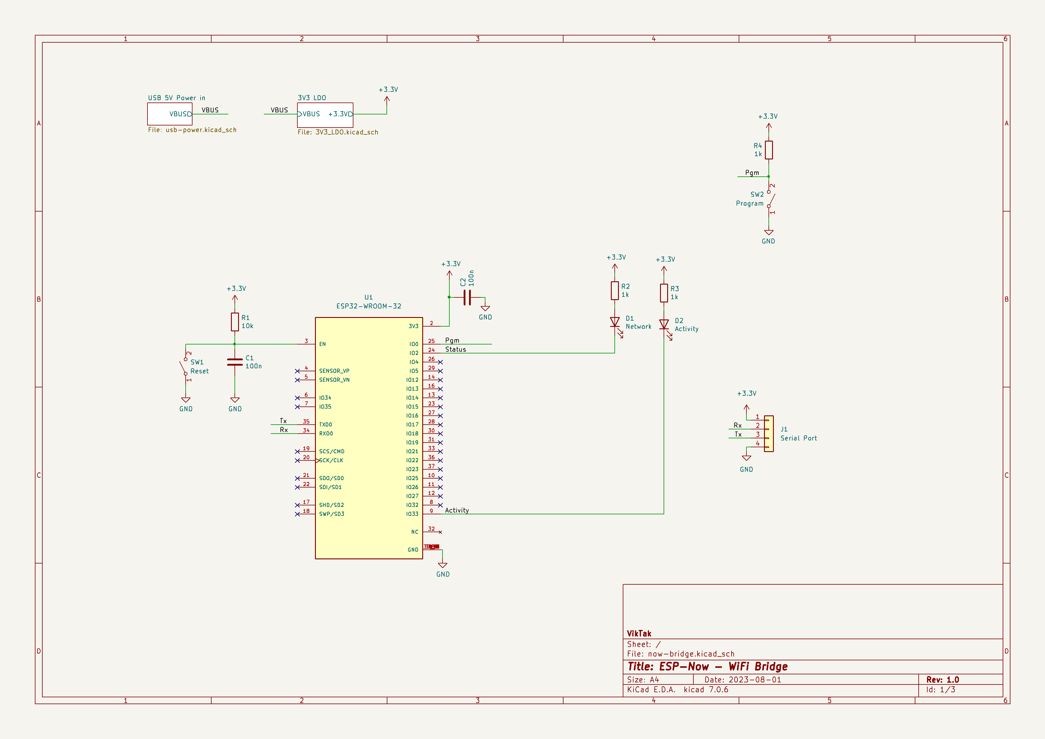
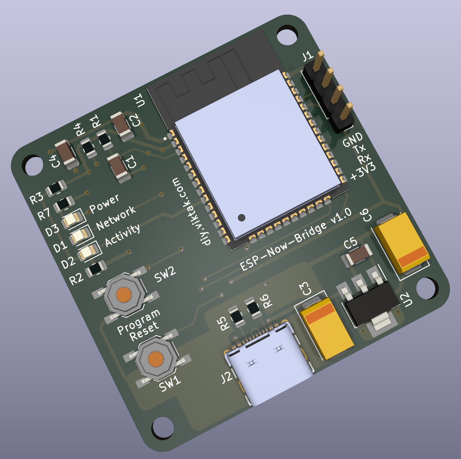
As you can see the circuit is very basic: Apart from the ESP32 we have a reset circuitry, a couple of buttons to facilitate development and a couple of status indicator LEDs: One shows when the device is connected to the local Wi-Fi network, the other one indicates ESP-Now activity.
Here is a 3D render of the board I designed:
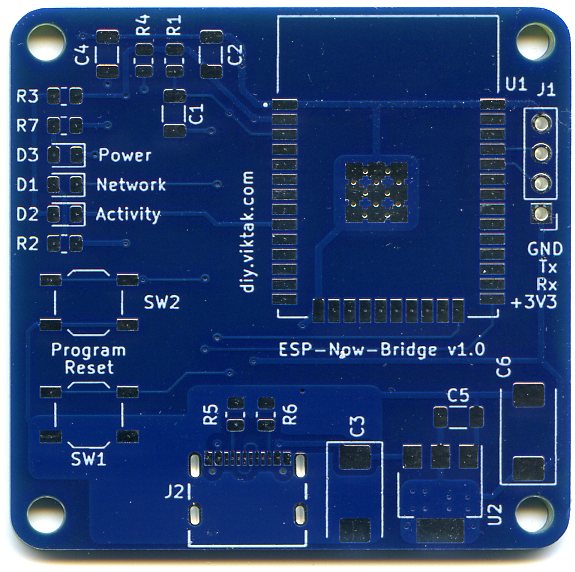
At this point I would like to thank PCBWay for sponsoring this project: Although it would be possible to make this PCB at home, I opted for a professionally made one by PCBWay. I have used them in the past with success and I knew that the PCBs I order would turn out great. The ordering process was smooth, and within 24 hours of ordering, the finished PCBs were handed over to the post. The PCBs arrived in perfect condition, with plenty of protection around them. The soldering pads were all clean and soldering was a breeze, no cleaning of the PCBs first was necessary. I also found out to my surprise, that even though I ordered 10 PCBs, I got 11 in the box. Awesome! If you also want your own light controller PCB professionally manufactured, click on the picture to the left and order your PCBs today!

When I received the PCBs, they were ready to be used, no preparations necessary:

The BOM is available in the project’s repo.
Firmware
The firmware is written in C++ using the ESP32 Arduino framework building on my previous similar projects. For me only the ESP-Now related parts were new – Again, I learnt something new! The sources are available here. At the moment it only contains the backbone of operations and a small section specific to a demo remote temperature sensor. It is now easy to add handlers for any new sensor. I plan to add plenty more in the near future.
As an example, a sensor message would look like this:
|
1 2 3 4 5 6 7 8 9 10 |
typedef struct struct_message { uint64_t ordinal; uint32_t nodeID; DeviceAddress deviceAddress; float sensorValue; uint64_t failuresCount; float batteryLevel; } struct_message; |
The ESP-Now protocol limits the messages transmitted in size to 250 bytes. This means we need to be very concise with our messages. In the above example you can see that only a handful of information is sent to the server. This is the breakdown of the set of values I found useful:
- ordinal: Shows the how many messages have been sent from the sensor since the last boot. Most of the time this is simply handy to know. When dealing with large payloads that span multiple data transmission cycles, it is critical in reassembling the original data (that was split for transmission).
- nodeID: This is the unique identifier of the node. I am using the ID of the ESP module – it is unique, so I don’t have to manage that myself. Based on this any business logic can be performed on the data received.
- deviceAddress: This is the ID of the actual sensor, if it has one. In the example above it is the unique identifier of a Dallas DS1820 temperature sensor.
- sensorValue: This is the actual reading of the sensor. I tend to have the sensors send raw measurements to save on power, but it is possible to send values that are already converted to something more meaningful.
- failuresCount: This shows how many times the sensor has not been able to communicate with the gateway. This can happen for a variety of reasons. Helps in troubleshooting.
- batteryLevel: This value shows how the battery is doing. I will elaborate on this more in an upcoming article when I will discuss actual sensors.
The task of the gateway is to translate this to a Json string and send it to the MQTT broker like this:
|
1 2 3 4 5 6 7 8 9 10 |
{ "Measurement": { "Ordinal": 60600, "Hostname": 13968968, "SensorID": "28:FF:8F:AB:54:15:03:C5", "Failures": 2529, "Value": 43.6875, "Battery": 3.948011875 } } |
In this example, for example, you can see this temperature sensor has been operating for just over 42 days on battery (assuming it sends readings once every minute).
Wrap it up!
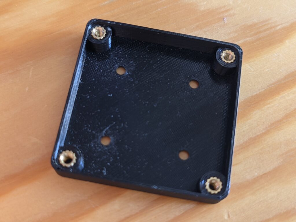
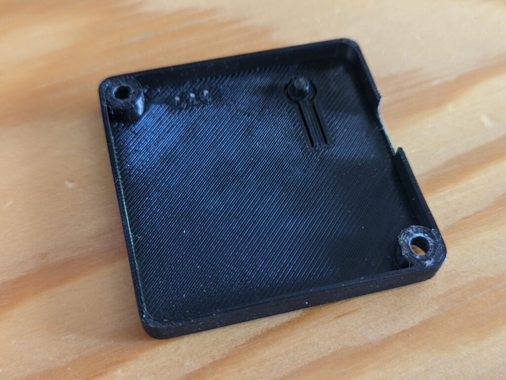
I also created a 3D printed enclosure for this gateway. Again, I used FreeCAD, because it is an awesome piece of software to quickly design custom enclosures for my circuits. Putting the PCB in an enclosure (even if it is a very basic one, like the ones I make) just raises the appearance of any project to a level where it becomes wife friendly. 🙂
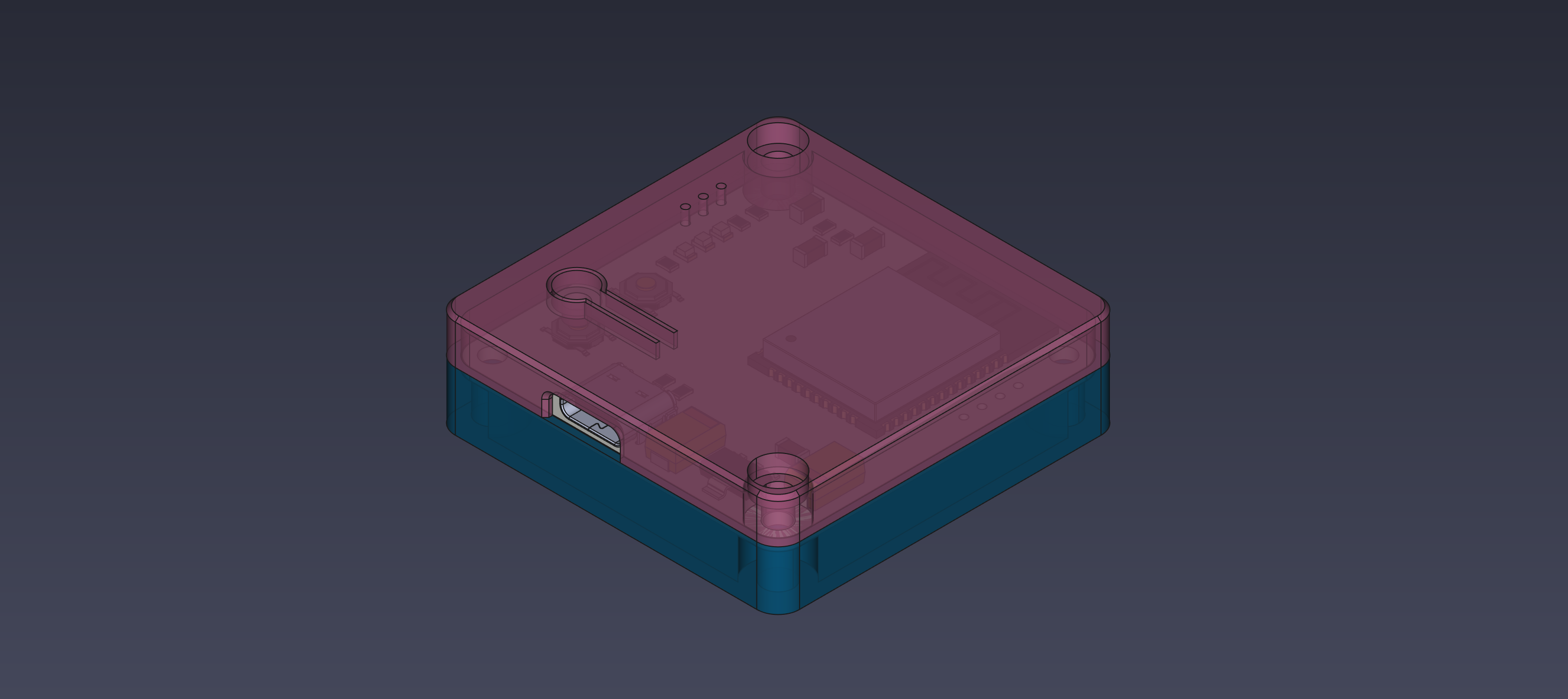
The STL files needed to print your own enclosure for this board is also included in the project’s repo.
Final result
All put together I got a neat little device about the size of a match box:
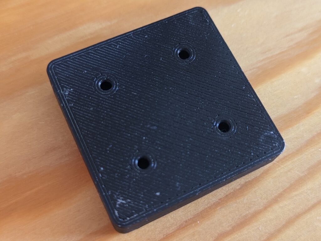
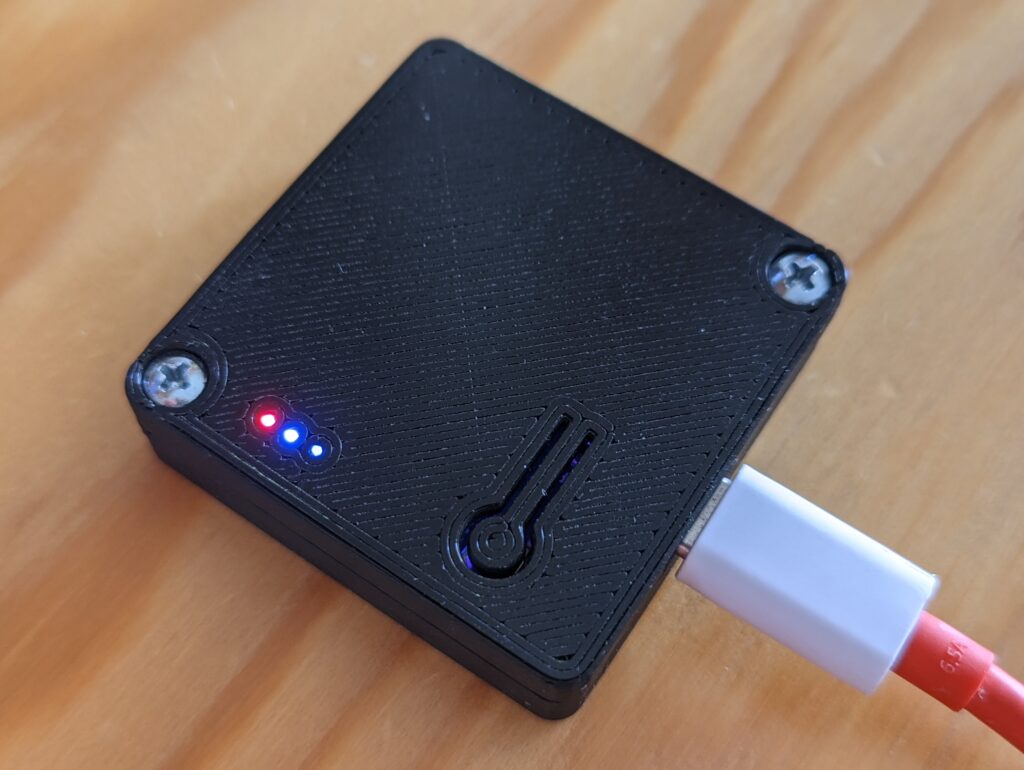
My favorite detail in this build is using SMD LEDs and a bit of optical fiber to conduct light to the front panel instead of using normal, 3mm LEDs.
In some of the upcoming articles I will present a number of custom sensors to be used with this gateway.

The Link the Repro ESP-Now-WiFi-Gateway is 404.
I’m sorry, I forgot to remove the private flag from it when I published this article. It should be accessible now. Thank you for letting me know!
THX
Sorry if my question will rub you the “wrong” way – would’ve you happen to have assembled ? I can program it myself. Thank you !
I just see your comment now – sorry.
Sure, please contact me directly for details.