I have long been looking for a way to make a word clock (although there is no shortage of clocks in our home…), but until recently I haven’t found a financially reasonable way to make one. What changed is that I recently acquired a desktop 3D printer. This dramatically expanded the capabilities of my home workshop. I can now easily make reasonably good looking enclosures, face-plates and other small, but essential parts for my projects. To make it more interesting for non-geeks, too, I included some features that are not obvious and I hadn’t seen in similar projects, such as easily replaceable template for letters, that allow the “clock” to be used as something else (maybe a menu, some other info board?).
When I set out to make this clock I had the following feature set in mind (and on paper – having it written somewhere also helps you not lose focus):
- No buttons, levers, dials, sockets, etc on the actual device – except for power connection. I was playing with the idea of powering the clock wirelessly, but the 143 RGBW LEDs at full power require a large amount of current that would be too bulky to transfer using wireless power transfer.
- Wireless connectivity using WiFi. This also allows the clock to synchronize itself with time servers on the internet. No more setting the time!
- Any and all configuration should be done in a web browser remotely, no extra software to download/install by the user.
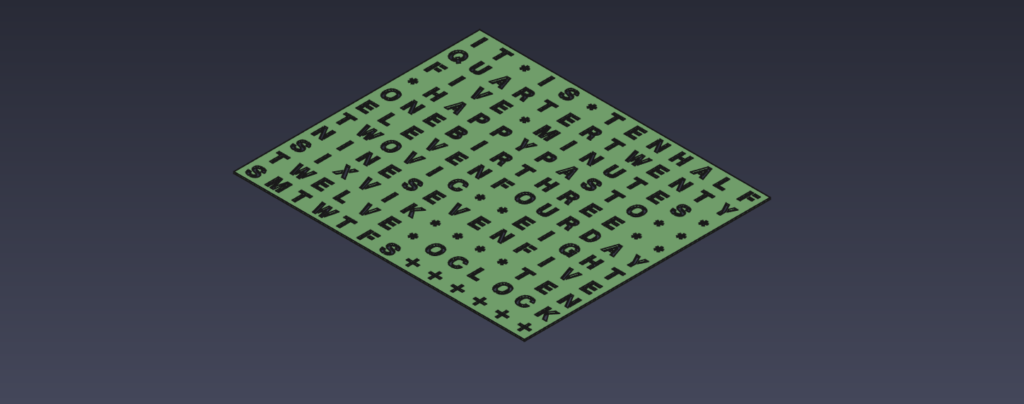
- There should be enough letters/characters to display not only the time, but some extra information, like day of the week, weather alerts, name days, or really anything that is available on the local network or the internet (I will show some examples later in the article).
- The letters should be replaceable with minimum effort if the user wishes to do so.
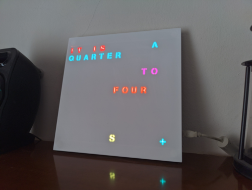
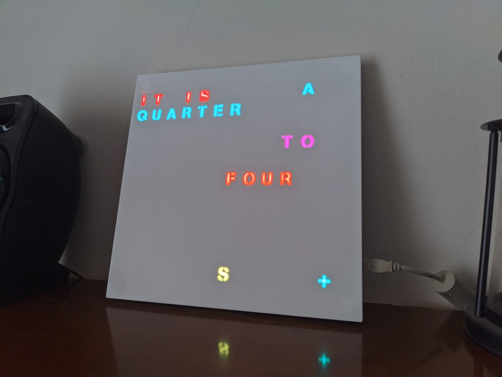
- Easy to read: I don’t like the design I saw (in some corners of the internet) where all the letters are visible all the time and the active letters are just lit up a little bit more. I think it is difficult to read, especially in a brightly lit room. In my design only the relevant letters should be visible.
Electronics
At the heart of this clock is an ESP8266 microcontroller. The actual circuit is very similar to the ones I used in previous (clock) projects: the letters displayed are lit by RGBW LEDs, just like in the recent Light Panels or last year’s Mirror Clock. Or at least, this is how I planned it. While I was waiting for the PCBs to arrive, however, I learnt that SK6812 LEDs perform much better in terms of color accuracy despite dropping voltage levels on a longer LED string. To my luck, they are pin and packaging compatible with the WS2812B LEDs, so I could use the same PCB. In the schematics, though, I still have WB2812B LEDs. You can use either as this LED string is not that long to make a difference.
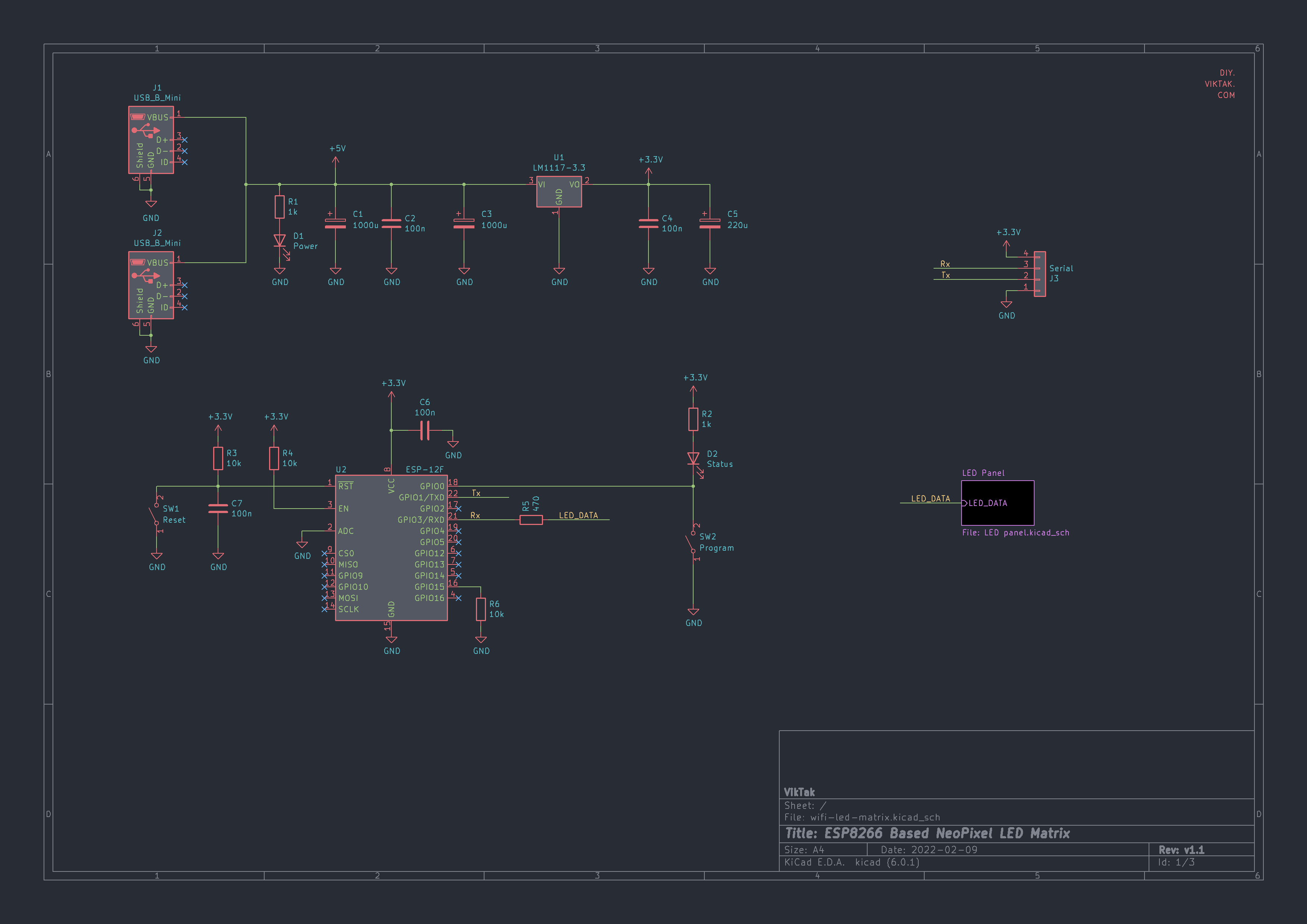
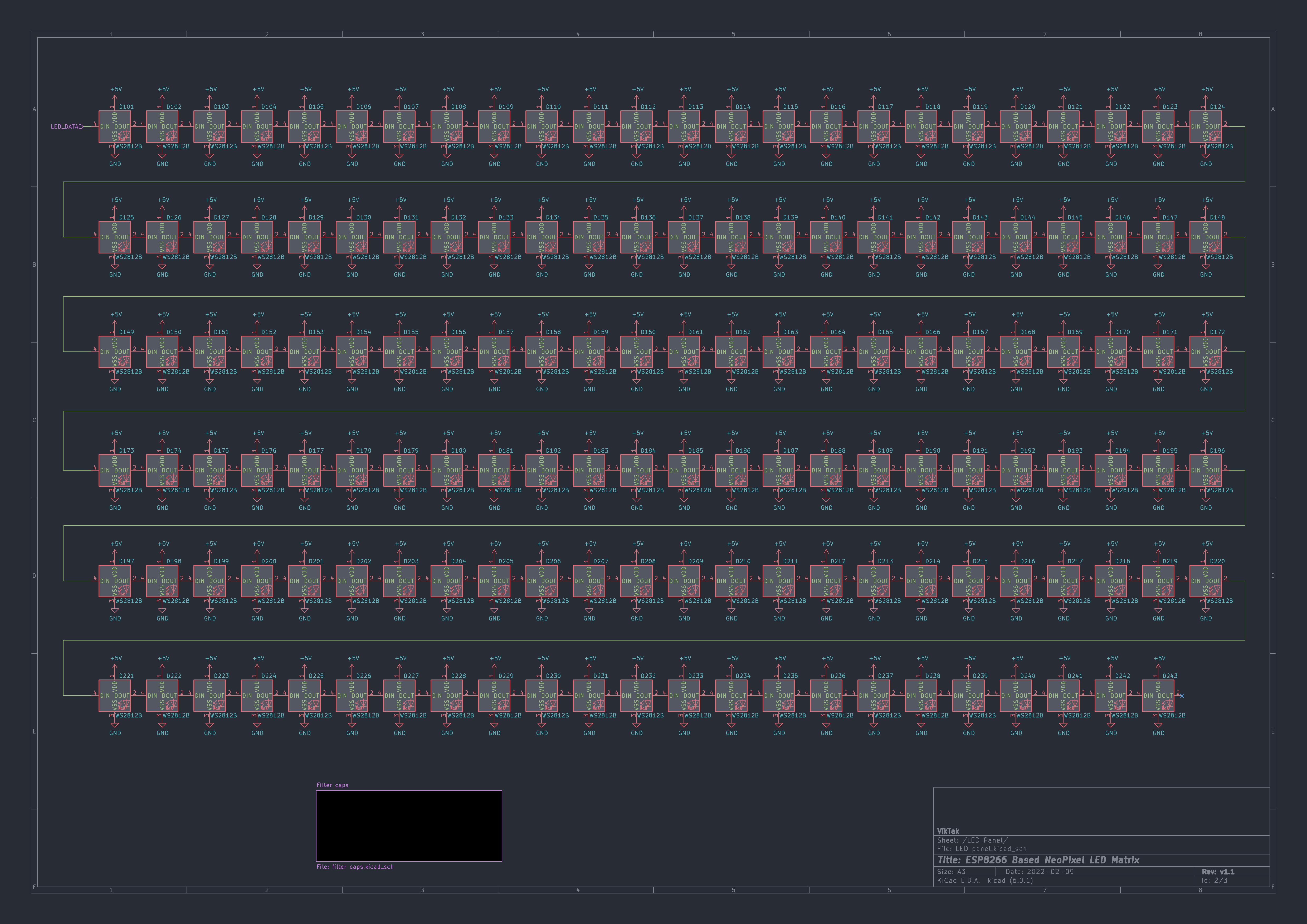
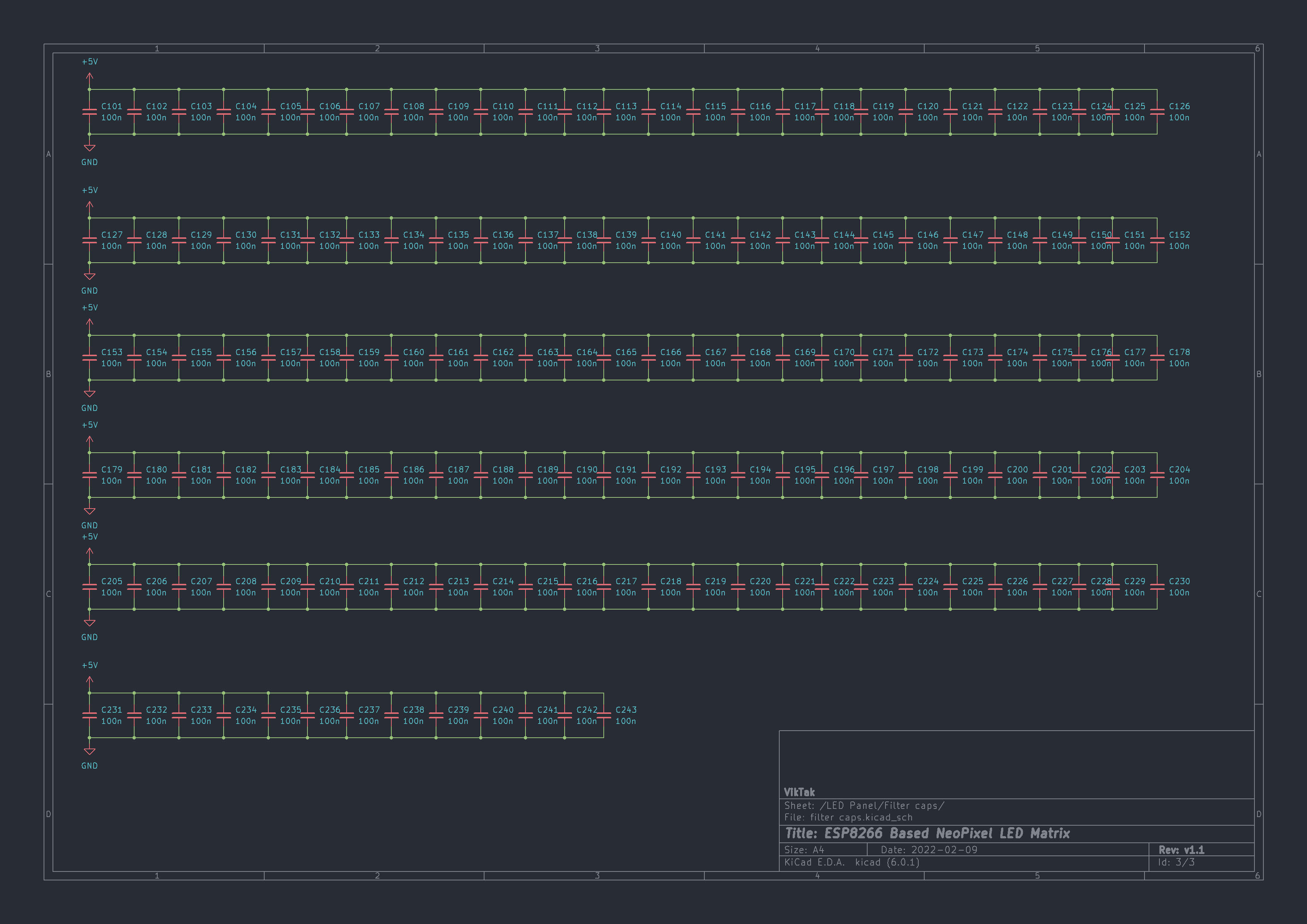
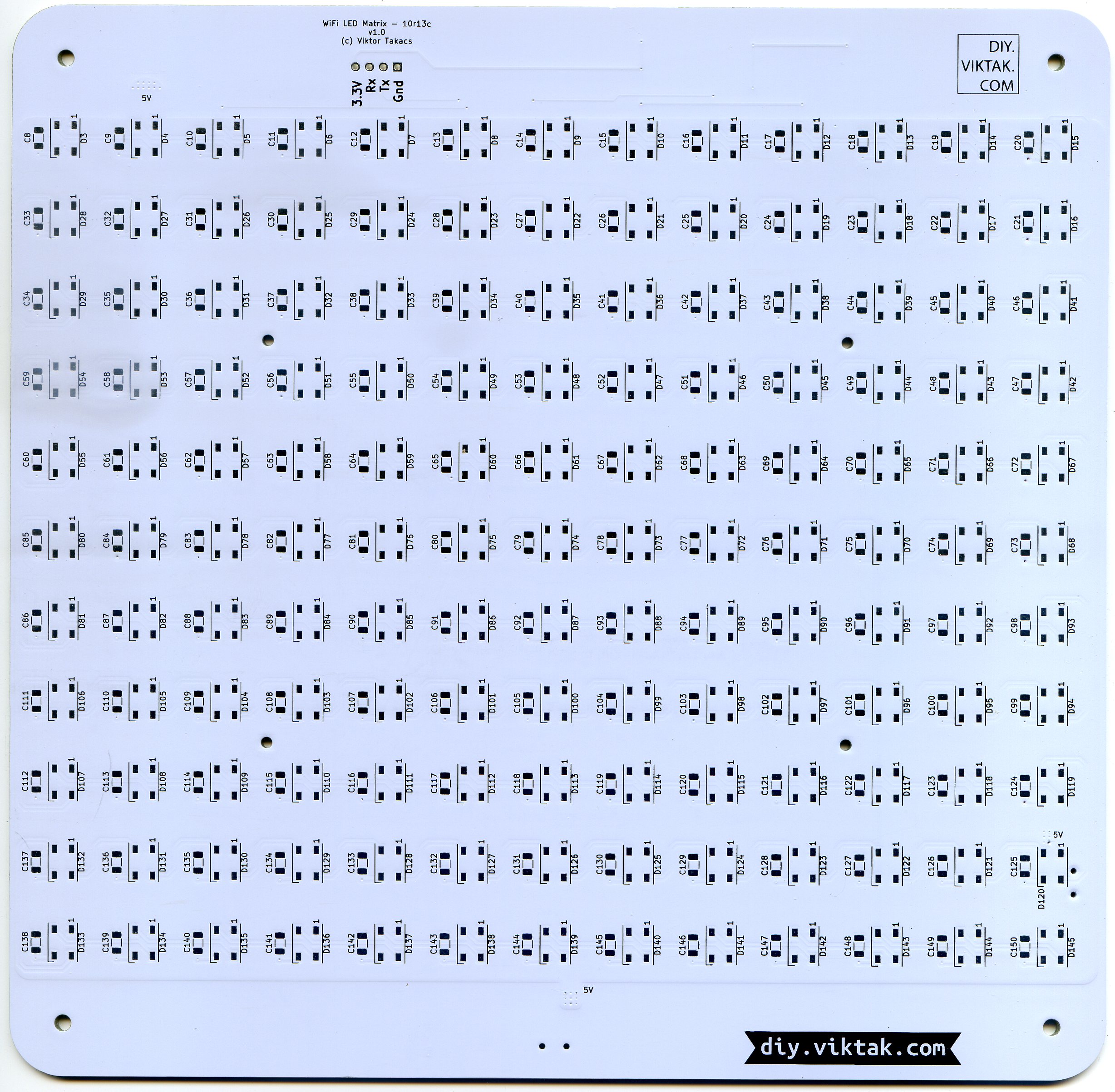
The most difficult part of creating the schematics was placing each LED and decoupling capacitor on the drawing board: the LEDs are arranged in a 13 column by 11 row matrix, totaling 143 LEDs and the same number of decoupling capacitors.
Printed circuit board
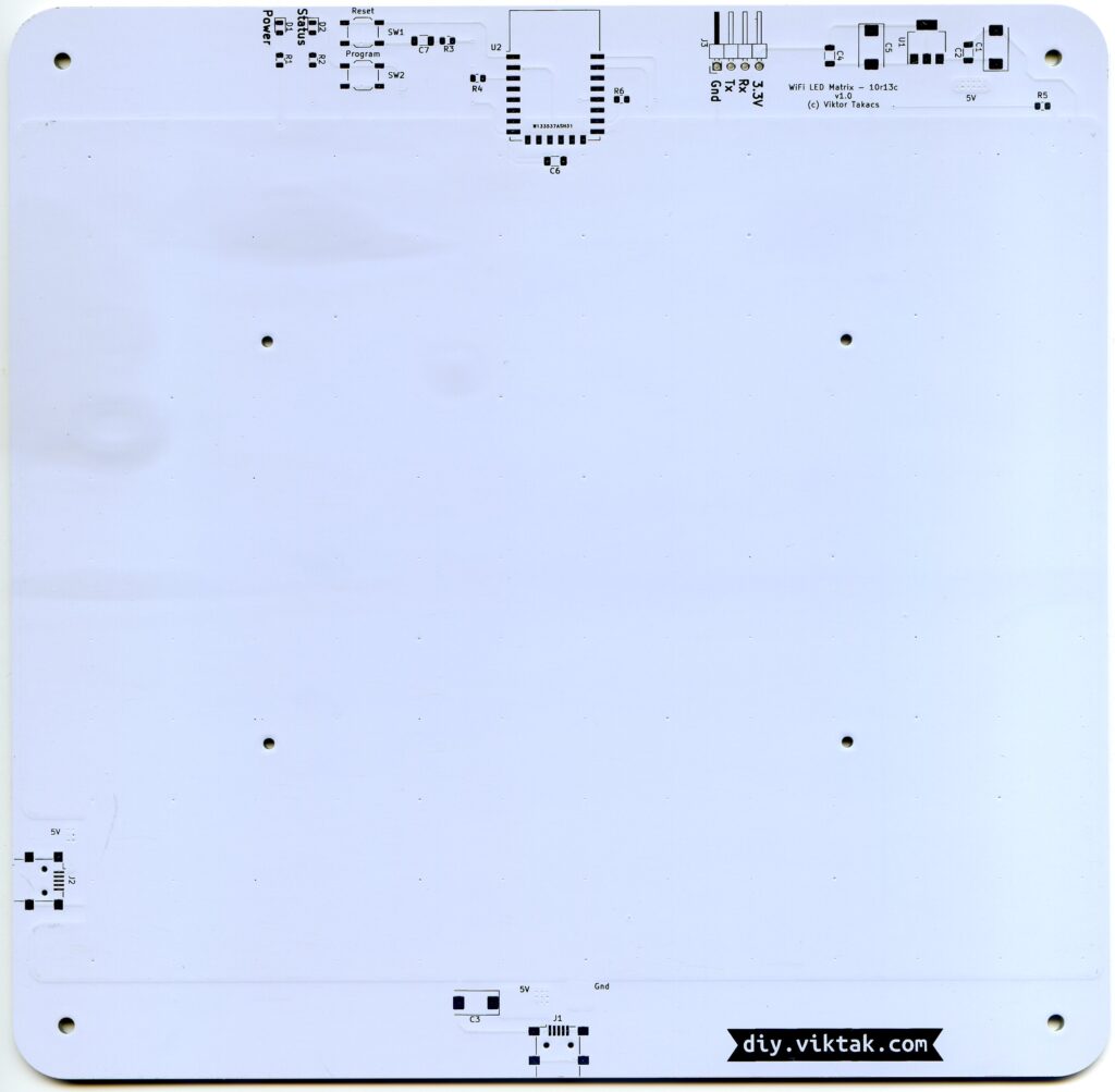
Before I created the first “PCB version” of this clock, I created a similar one, that did not use a PCB. Well, there was a PCB, but it was a generic PCB I had left over from a different project. in this “test” version I soldered all the LEDs to long stretches of copper wire, which created the frame of the matrix. This version worked really well, from a functional point of view I have no complaints. However, soldering all the LEDs together was not something I wanted to repeat over and over again. As I plan on making several of these clocks for friends, family, and anyone else who is interested in it (hint, hint… 🙂 ), at the end I designed a custom PCB that would hold all the parts: One side the LEDs and filter capacitors, the other side all the other bits and pieces:
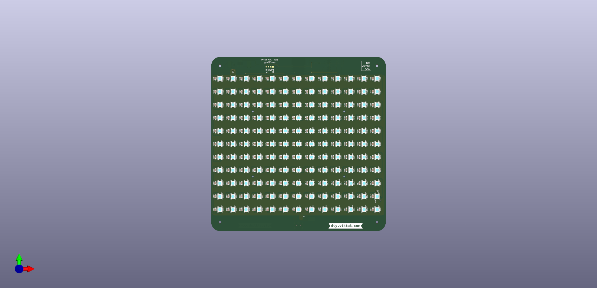
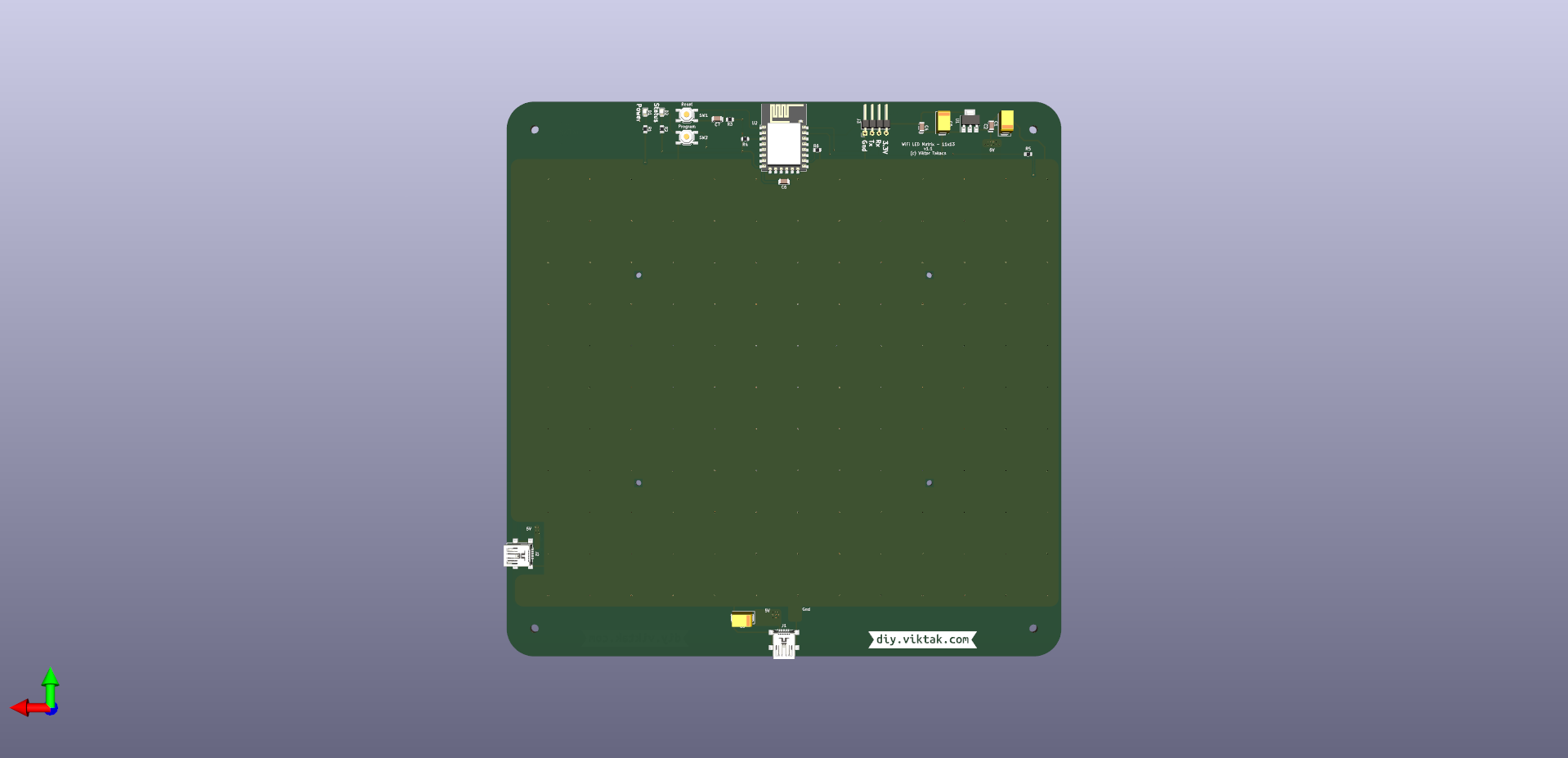
The PCB is 200mm*200 mm. You’ll notice that there are 2 micro USB sockets on it. This is to accommodate wall mounting (powered from the bottom socket) as well as table-top placement (powered from the side socket).
Both a ground and a 5V pane is used on the PCB to minimize power drop between the first and last LEDs as well as helps cooling the panel. It also helps distributing the relatively large currents evenly to each LED.
I chose white silk screen to maximize the LED power that reaches the face-plate, just like in previous lightning related projects.
One difficulty to tackle when using large PCBs is that when soldering by hand, the difference in temperature between the spot heated and the rest of the board can easily lead to warping. Using a hot plate or a (home made) reflow helps to keep the board at a uniform temperature thus preventing warping.
No sponsors

This project was not sponsored by a 3rd party. However, I opted for PCBWay’s services because this PCB needed special care: At 200mm*200mm it is probably larger than most hobbyist panels, certainly one of the largest PCBs I have ever (had) made. For example, a large PCB easily bends when not heated uniformly. When the PCBs arrived I was pleased to see that all of them were completely flat.
Also, I placed some positioning holes on the the board where it would be mounted to the enclosure (see further down the article). The holes aligned perfectly making the assembly a breeze.
I also had some questions around the PCB stencil at ordering which I got quickly sorted out in a quick chat with PCBWay.
If you also want your own custom PCB professionally manufactured, click on the picture to the left and order your PCBs today! Or click here to order your PCB for your own WiFi LED Matrix!
Firmware
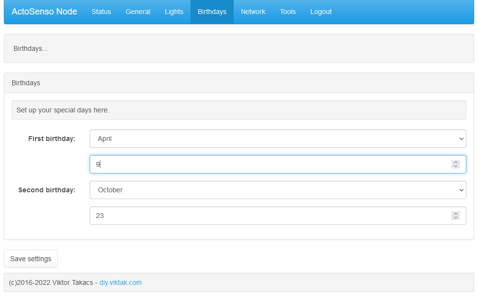
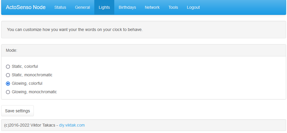
Most of the firmware is reused from my previous projects. The new settings pages of the built in web server are for setting two special days when extra effects are played throughout the day and the general look and feel of the displayed text:
Operation
This is a high level overview of the operation of the clock:
At power on it reads settings from any previous operations or the default values. Then it tries to connect to the last used WiFi network. If it cannot, it reverts to Access Point mode, creating its own WiFi network that can be accessed from any WiFi capable device (laptops, smartphones, etc) to connect it to one’s WiFi network. Once connected, it fetches the time from a pool of public NTP servers. This ensures that there is no need for the user to set the time. During normal operation, it synchronizes the time several times the same way.
By default, it also connects to an MQTT broker for interoperability with other IoT devices (more on this later). This functionality is easy to disable in code if needed.
Based on the settings on the “Lights” page, it displays the time using words, as any good word clock would do. 🙂 At the moment only a few display modes are implemented, more are coming later. My favorite one is where all the words have a different color (picked randomly at system boot), and all words kind of glow (slowly changing intensity). See video below.
Throughout either “special day” selected on the “Birthdays” page, every once in a while, instead of the current time, an animated birthday message is displayed.
I wrote the firmware for the ESP8266 in the Arduino framework. The sources are available in my GitHub repo.
Extras
Here is the “extra” from the article’s title: Any of the 143 LEDs can be used as a “semaphore” to show some kind of status information. Currently, the firmware is set up in the following way (but it is very simple to modify): The first 10 rows are used to tell the time and birthday wishes. The first seven positions of the last row are used to show the day of the week, and the rest are used to display various binary information, like “Severe weather warning in the area in effect”, “Home Assistant update available”, “Pi-Hole update available”, “Full moon”. Any status information can be displayed this way. Colors can also be employed to convey certain information, which means non-binary information can also be displayed.
Enclosure
I have iterated through a number of designs for the enclosure. I am still new to creating mechanical designs, getting my grips on FreeCAD, learning best practices in industrial design and 3D printing.
The design I settled on in the end consists of a number of distinct parts, each printable separately by the average desktop 3D printer. From front to back these are:
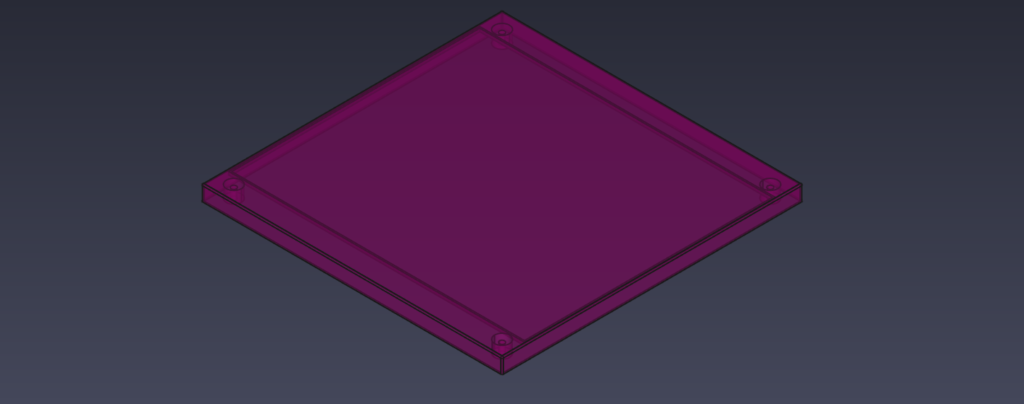
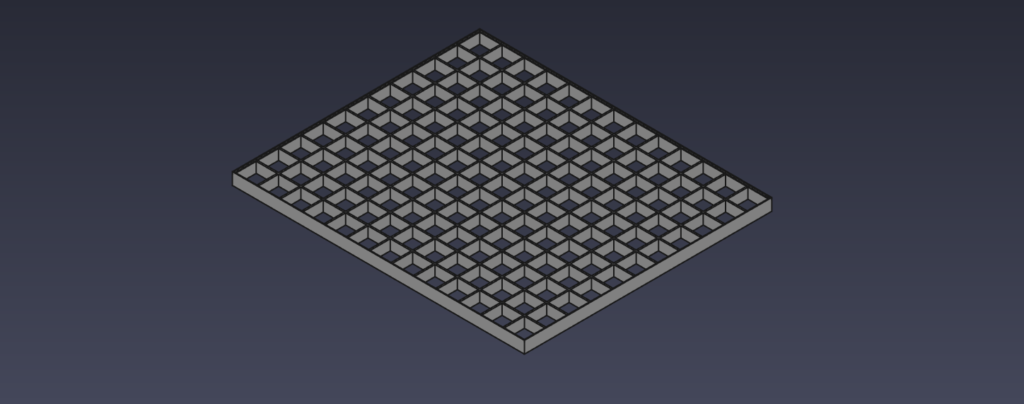
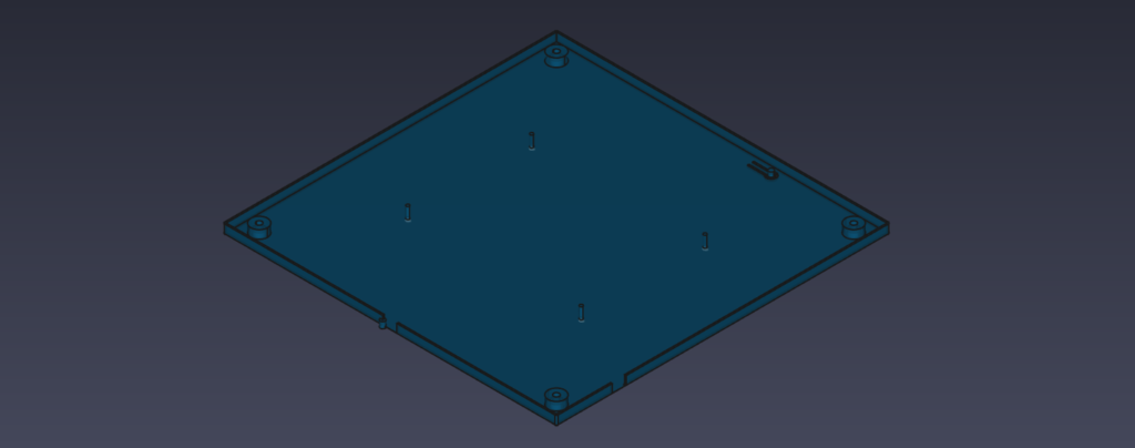
The PCB with the LED matrix is sandwiched between the back cover and the separator. the whole assembly is held together by 4 screws in the 4 corners. The inside of the diffuser has 4 knurled brass nuts (I’m not particularly sure about their names..), that were inserted carefully into their holes using a soldering iron which melted the PLA just enough to take the nuts.
It took me a couple of iterations to get everything right, and I really like the end result, which is as minimalist as it gets – when the clock is not powered on, only a white square is visible, no letters, no switches, no knobs, etc.
Summary
I am quite pleased with the result: I accomplished all the goals of the project while learning about handling, soldering large PCBs, designing an enclosure that is not sore on the eyes, and 3D printing parts for the enclosure.
This RGBW LED matrix can be used not only to display time but to display arbitrary messages, tip of the day, even a menu in a restaurant, the specials in a bar, etc.

Hi,
I’m very interested in your FreeCAD file ” https://github.com/viktak/FreeCAD-scripts/blob/main/WC-CreateFacePlate.FCMacro“,
but that websilte isn’t there anymore.
Can you help?
Thanks,
Leendert Vermeulen
The Netherlands
I just see your comment now – sorry.