This article is a new iteration on the wall clock I made a while back. (What can I say? I like LEDs, clocks and clock made up of LEDs…) This time I used a new PCB for driving the circuit and I designed a fully 3D printable enclosure for it instead of the IKEA frame. Although I lost the “mirror” look of the clock, I gained a different look that I can customize completely to my needs.
Schematics
The schematics of this clock is very similar to the previous one. I only drew a new one because I moved from Eagle to KiCad. This project was a good opportunity to learn KiCad, because the schematics itself was ready and I could focus on learning KiCad.
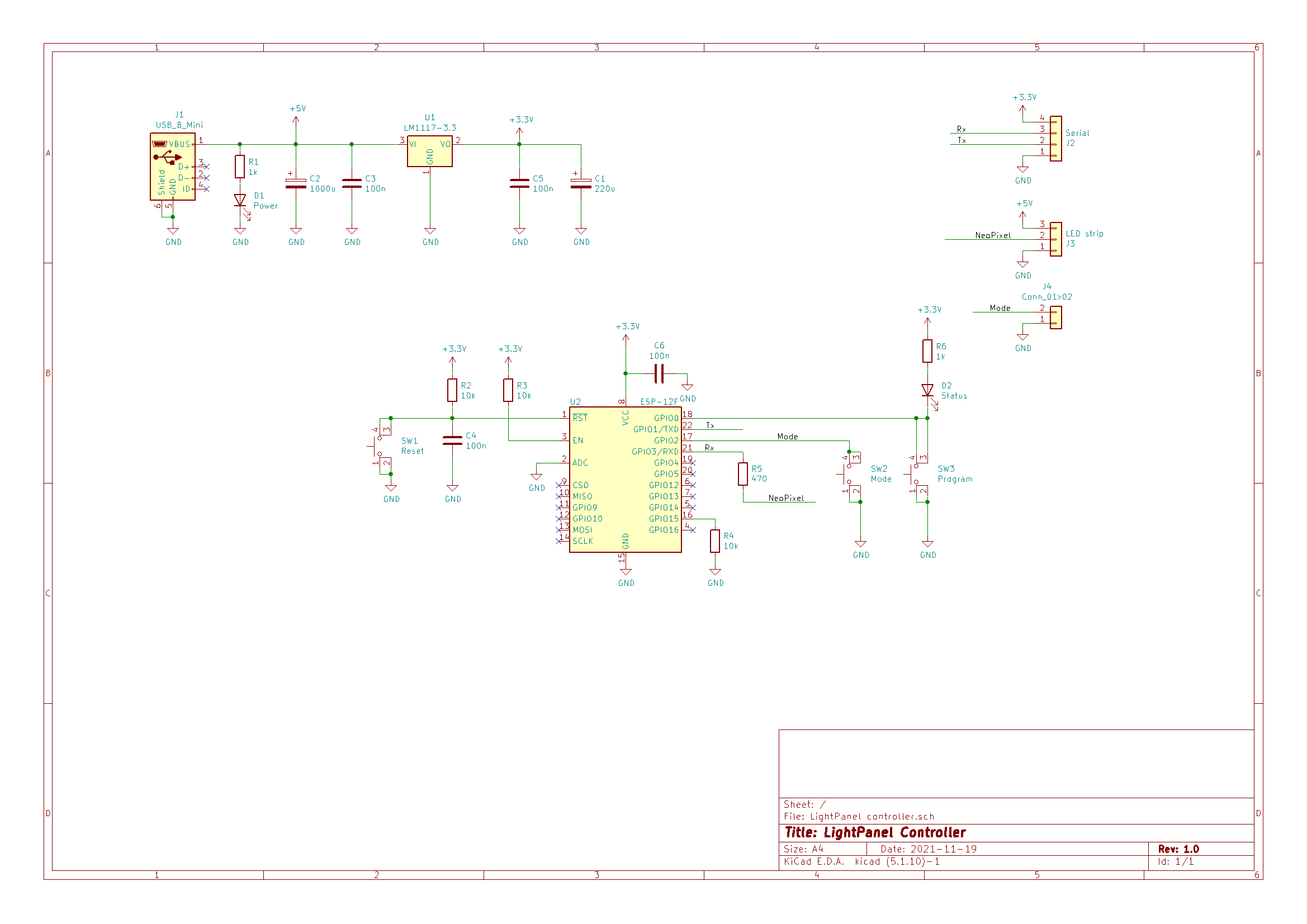
The circuit contains little more than an ESP-12F device and the “standard” accompanying parts. For details you can check out my previous projects with similar schematics.
It is worth mentioning that the USB socket is NOT used for powering the device. Also, switch SW2 (Mode) can be omitted from the final board. These parts do not need to be soldered on the board, as they are not used in this application. I use them in other projects of mine. The reason for my soldering them to this board is that they were useful for the first programming of the CPU and the first experiments before the board was finally mounted its place in the 3D printed frame.
PCB
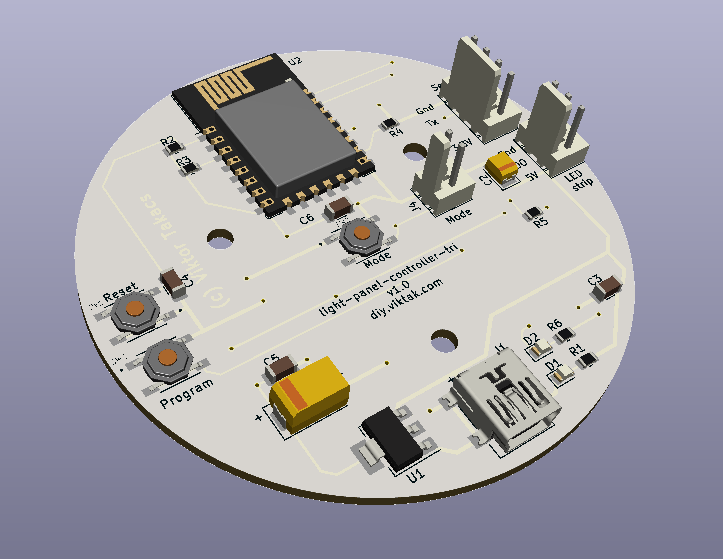
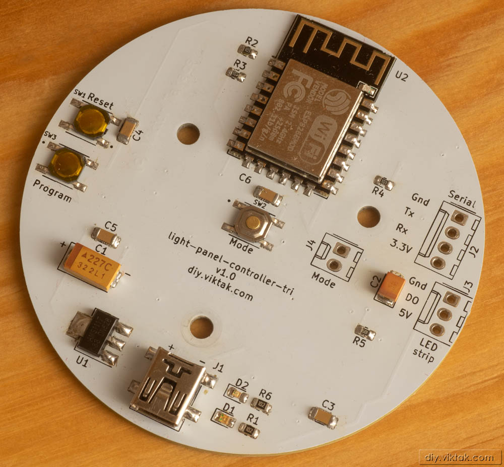
For this project I used a custom PCB that I designed for this project and some other ones I had in mind. It is a circular, white PCB:

A word about the sponsor of this PCB: Although it would be possible to make this PCB at home, I opted for a professionally made one by PCBWay. I have used them in the past with success and I knew that the PCBs I order would turn out great. The ordering process was smooth, and within 24 hours of ordering, the finished PCBs were handed over to the post. The PCBs arrived in perfect condition, with plenty of protection around them. The soldering pads were all clean and soldering was a breeze, no cleaning of the PCBs first was necessary. I also found out to my surprise, that even though I ordered 10 PCBs, I got 11 in the box. Awesome! If you also want your own light controller PCB professionally manufactured, click on the picture to the left and order your PCBs today!
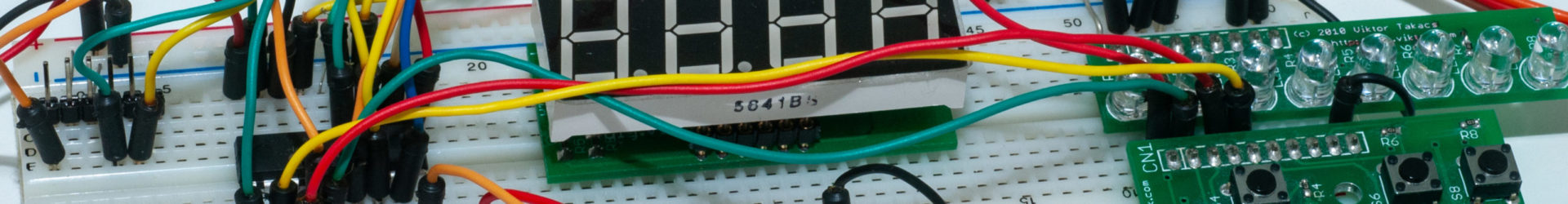
There is nothing special about this PCB. Most parts are surface mount parts. The only ones that are through the hole ones are the programming header and the header for the light strip, which in this case is a ring of 60 WS2812B LEDs. As such, they are not even needed in this application: The programming header is only used once to initially program the ESP chip (any subsequent updates can happen over the air), and the solder points for the light strip directly takes three wires.
Order your own PCB here!
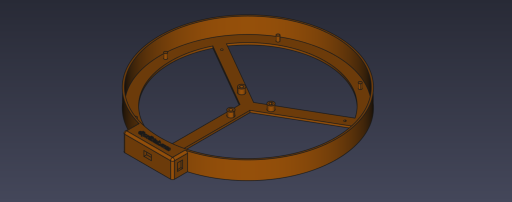
3D printed frame
For me, the most interesting and challenging part of this particular build is the 3D printed enclosure of the clock. I recently acquired a 3D printer and this project is one of the first ones I did using it. In fact, a big part of why I wanted to do this particular clock is so that I can learn to create a 3D printed enclosure for it.
I used FreeCAD to design the parts of the enclosure. The complete design consists of only three 3D printed parts:
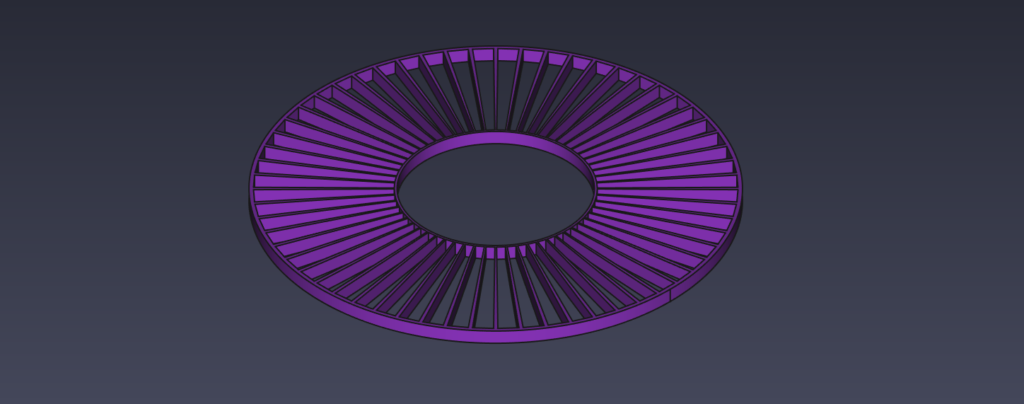
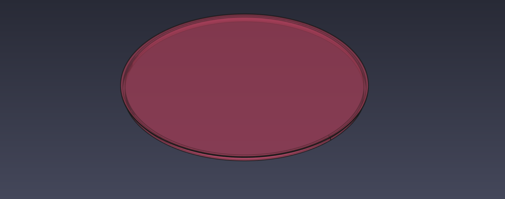
The 3D printable parts are available here and here and here.
Assembly
Putting all the pieces of this project is really simple. All the 3D printed parts are designed and printed to such tight tolerances that they hold together once they are put together (friction fit). They are also available for download in the project’s repository.
The base contains 3 openings for a barrel socket, two on the sides (for having the clock on a flat surface) and one at the bottom, in the center (for hanging the clock on a wall). In my prototype I mounted all three of them for demonstration purposes, but it is really not necessary. The power sockets are held in place with a generous amount of hot glue:
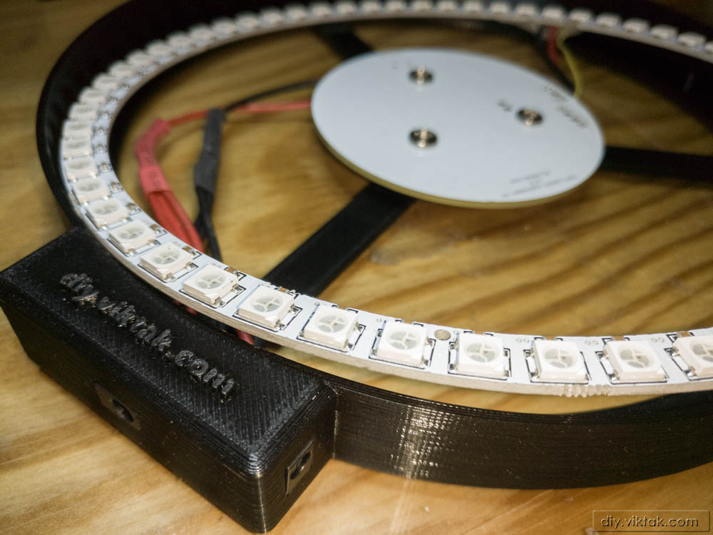
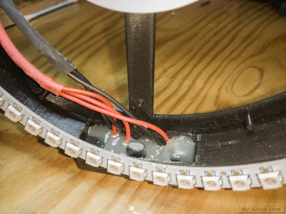
The power sockets are connected with the control board with short pieces of wires capable of handling at least 2A (lot of margin for safety).
The control board is also connected with the LED ring with short pieces of wires:
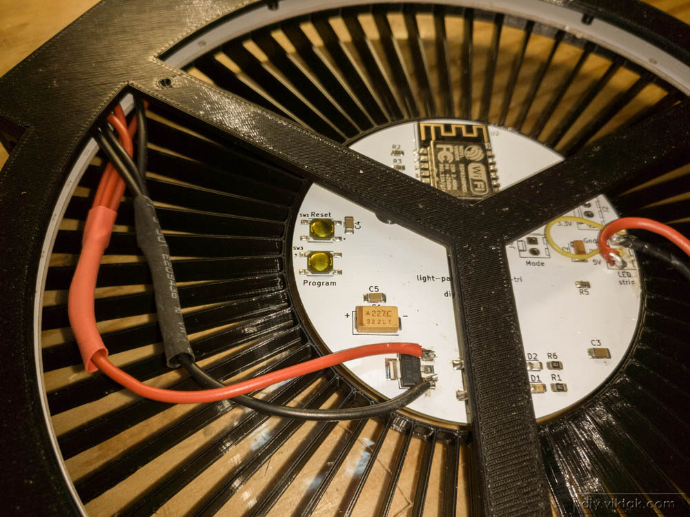
The base has three mounting pylons that align with the three holes on the PCB for easy mounting. To avoid the Power and Status LEDs’ light show up on the face of the clock I mounted the PCB upside down.
Firmware
The firmware is identical to the one I used in the previous iteration of the clock. It can be downloaded from the project’s repository.
Here is a quick timelaps video of the clock in action:
Summary
From an electronics engineering point of view, this project contained little if any new elements for me, but it was a fun project to do while learning about 3D printing. And now I have yet another clock at home!

test comment
Good job, can I replicate this? Do you have 3D models that I can print? I browsed the repository but I can find these.
I just see your comment now – sorry.
Of course you can replicate it! When you do, please leave a comment here to show your version off!
I have now included the information on the printable files.
This RGB clock tutorial looks awesome! The step-by-step instructions make it seem so doable. Can’t wait to try building one myself—love the vibrant lighting effects!
Don’t forget to send me a pic or two of your version so that I can show it off here, if you want!!!!