Introduction
For some time I have been planning to build a number of devices that make use of stepper motors. Since I have no experience in using stepper motors I had no idea what parts, what driver and controller circuits I would need to get them running.
After extensive research on the internet I decided to make a bipolar stepper motor driver based on Texas Instuments’ LMD18245, which is a 3A, 55V DMOS Full-Bridge Motor Driver. It incorporates all the circuit blocks required to drive and control current in a bipolar stepper motor.
This integrated circuit is a bit more involved to program (although surprisingly simple compared to what it delivers) but comes with many extra features (for free), such as overcurrent protection and thermal shutdown.
Creating a test board for the LMD18245
The only drawback of the LMD18245 is that it comes in a 15-pin TO-220 package which is not breadboard-friendly. To overcome this problem I designed a small breakout board for the chip:
 |
| R3 and C5 are placeholders on the PCB to achieve more precise component values. |
It has footprint for all the parts needed for normal operation or experimenting with the LMD18245. It also has a 15 pin header to allow easy access to each pin of the chip.
A little detour to using someone else’s custom part – I don’t want you to make the same mistake as I did!
I designed the circuit and PCB in Eagle. Eagle doesn’t come with the part for the LMD18245, but a quick search on Eagle’s web site made me happy with a part someone had made available as a free download. As usual, after downloading it I double checked the footprint used against the datasheet and found it correct, so I started designing the circuit with it. I even printed the PCB artwork on paper (as usual) to check it against the actual parts I would use to populate the PCB with. Everything checked out, so I sent the gerber files for production.
 |
| Front of finished PCB |
 |
| Back of finished PCB |
After a few weeks I was happy to receive the ready boards and I started assembling two of them (two LMD18245s are required to drive one bipolar stepper motor). Soon I realized that, although the footprint of the LMD18245 were correct, the holes for the LMD18245 were too small. That means all the holes had to be enlarged. Luckily, I have a small drill and drill bits as small as 0.3mm diameter, so I picked a 0.8mm one and widened the holes as can be seen in the images below.
 |
| Front of corrected PCB |
 |
| Back of corrected PCB |
Lesson learnt: NEVER trust a custom part unless you fully check ALL its properties!
and now, back to the project…
 |
| Close-up of a fully populated LMD18245 breakout board in the test environment |
Test application
To test the breakout boards I created a simple circuit around a PIC18f4550. Since the circuit is very simple, I didn’t create schematics for it. I used PORTD[0..7] to control the M1..M4 lines of the 2 LMD18245, and used PORTA[0..1] to control the two direction lines. I also have 8 LEDs on the test board to show me what lines (PORTD[0..7]) are active. The circuit works just fine without them as well.
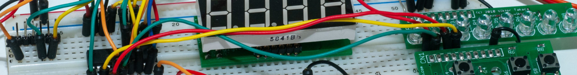
This is the full setup:
 |
| The rubber band on the motor is placed there to prevent damage to my desk in case it resonates much. In practice, it’s hardly noticeable. |
Building blocks of my test rig:
- NEMA 23 stepper motor (left)
- PIC18F4550 (center)
- ICSP connector (above the PIC) – it’s a 6 pin RJ45 connector.
- 2 LMD18245 breakout boards (lower left)
- 8 debug LEDs (top right) – optional
 |
| Close-up of the breakout boards. |
Test run
I powered the motors with a 12V ATX power supply as that’s all I have available at the moment. I understand if I used higher voltage (up to 55V) The motor could run faster, but I cannot test this right now.
For any real life application the LMD18245 needs heatsinks. In the test rig, however, I observed that as long as the axis is in continuous movement there is no heat dissipation almost at all. Even after hours of running the chips are all at room temperature. When I slow down movement, i.e. making small breaks in between steps, the chips start heating up.
The alligator clip on the axis of the motor serves only one purpose: makes motor movement visible. 🙂
A few test videos in different setups, all full stepping mode:
Step by step
In this video you can observe each step individually, with a bit of pause in between steps.
Continuous movement in one direction
This video shows how smooth in goes in one direction. There is no noticeable resonance coming from the motor, it really runs very smoothly.
Circling back and forth
In this video the motor takes one full circle (200 full steps) in one direction, makes a small pause, then does the same in the opposite direction, all at full speed. Again, movement is very smooth, only at start and stop you can notice some shaking of the motor body.
Where to go from here?
Implementing microstepping to make movement more granular, more precise and less shaky should be easy, I just need to develop further tables to control the LMD18245.
I am planning on using the knowledge and experience gained in this experiment in several future projects. I currently have plans for a CNC machine and a time lapse rig for cameras.
Stay tuned!
