Introduction
I am a regular on eBay and 99% of the time I successfully source items from China. The key for this success rate is knowing what to order and what to expect for your money. However, recently I ordered a number of test leads from China for about USD2.50 for 10 pieces. My thinking was like this: What can go wrong with a piece of wire? Now I know: a lot!
First impressions
When the test leads arrived I was happy with them, they all looked OK. Nice, colorful leads, complete with insulation on the clips:
 |
| I borrowed this image from a random auction on eBay. |
However, at close inspection the wires felt a bit soft. At the beginning I didn’t pay much attention to this, as I still thought: what can go wrong in with a piece of wire.
Using the original test leads
In most of my projects I use small amounts of current, so for a while the only thing I noticed about these wires is that the joints (where the wires meet the clips) are very flimsy. I easily fixed that with a dab of solder every time a test lead lost connection. And I thought that was it. I couldn’t have been more wrong!
In a recent project of mine I was working with currents of up to 4 amps. At some point the circuit didn’t behave as it should have: despite all the obvious measurements, calculations, checks and re-checks, Ohm’s law didn’t seem to work. To top all this, one of my test leads burnt my hand when I accidentally touched it (through the insulation!). Frustrated as I was, I started to measure and check the non-obvious parts. It turned out that the test lead had 0.5 ohm resistance. With the 3 amps flowing through it it dissipated 4.5W of power! Wow!
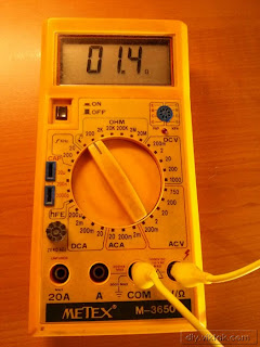
To see if this was the only bad cable I had I started to measure all the other test leads in the bunch. The results were quite disappointing: the resistance of any test lead was anywhere between 0.5 ohm and 1.4 ohm. see some examples below:
After the measurements above it became very clear to me that these test leads are not usable at all. I thought I could still use the alligator clips at the end (although they are not very sturdy either). But I needed some wires and this time I wanted quality ones.
I was a bit lost finding suitable wires, but then it occurred to me that I have many (i.e. tens of) computer/monitor power cables, like this:
 |
| Some even have the protective caps – most of them have never been used. |
Since these plugs cannot be used in Greece anyway (they are from Ireland where I used to live) they were my first candidates for recycling. The fuses inside of these plugs are rated 10A, so the wires inside should be more than adequate for my projects.
Making the new test leads
I followed the next few steps to make the new test leads:
- Cut the plugs off the power chords and remove the 3 individual wires from the insulation.
The difficult part is to open the first few cm-s of the insulation. After that you can just grab the inner wires in one hand, the insulation in the other and can pull the whole thing out in one move. - Pick a color to work with (available colors: blue, brown, green/yellow) and cut it to size.
- Clean the clips (or banana plugs if you have that) from the original wire.
- Solder in the new wire.

Don’t forget the insulation caps before the soldering…
This is a series of short videos showing some of the above process:
Results
The result is that now I have proper test leads with resistance of less than 0.1 ohm per meter.
This is a measurement of one of my new test leads:
 |
| This test lead is more than double the length of the one measured before and its resistance is much, much less. It would dissipate less than 1W @3A. |
Also, with this method now I can have as many test leads of any length as I want. All this with recycling old materials in my home. And a few minutes’ work.
I think it’s worth it!


Good idea, I wound up doing pretty much the same with a set of leads I picked up for work.
If you'd like to make more accurate measurements (and because diy test gear is cool) do a google search for 'diy low ohmmeter'. Here's a quick sample:
http://electronics-diy.com/electronic_schematic.php?id=951
There's a bunch out there. Most use a constant current of 100mA or 1A and (carefully) measure voltage using a technique called 'Kelvin measurement'.
Good idea, I checked it out. However, I don't think I will bother…. It's good enough for my projects now. It's good to have the option, though….
Been there, done that. I used wires from old ATX power supplies. They are also speced for over 10 A, have decent insulation and come in a variety of colors.
Yes, they are also good ones, the only problem with them is that they are short. Obviously, 1+ meter long test leads are not always necessary, so one could live without them.