I have been using a cheap, no-name wifi repeater in our house for about a year. It is of the type that you plug in a mains socket on the wall (after configuring it with a computer) and you forget about it. It’s done a good job (i.e. zero maintenance) until a few days ago, when one day I realized it was not working. Only its red power LED was blinking, and we all know the red lights, especially blinking ones mean no good.
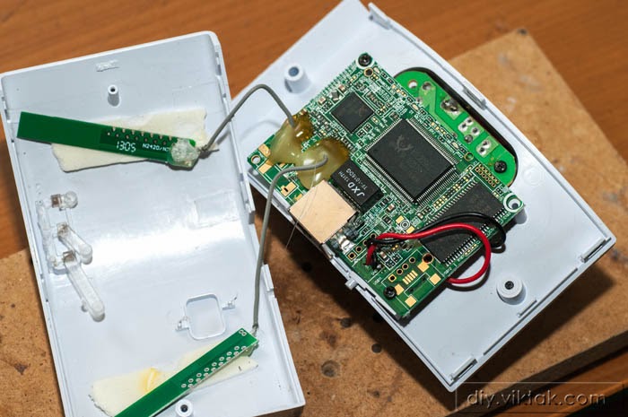 |
| The two antennas are stuck to the back of the front panel. |
Since it’s a cheap model, I immediately ordered a new one, but it would take several days to arrive, so I decided that before throwing it away, I would open it up and see what’s inside, how it works, and maybe salvage some of the internals for later projects.
Investigating the internals
There are several flaps around the edges of the enclosure holding it together as well as a screw hidden under a sticker that holds the serial number, default IP address and some other basic information. I found out about the screw by gently swiping the sticker with my thumb and I felt the hole in the middle. Once the sticker and the screw under it was removed, the two parts of the enclosure came off relatively easily.
 |
| Wifi board removed, the back of the power supply board on the right. |
Inside I found two printed circuit boards (PCBs). One was the wifi board with the famous Realtek chips RTL8196 and RTL8192 that handle network communications and another one that was the switch mode power supply that allowed the device to be plugged in a power socket and be operated from mains.
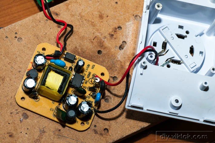 |
| The power supply PCB removed from the shell. |
I hoped that only the power supply board went bust. I disconnected the wifi board from the power supply board and applied 5V DC to the same points where the power used to go from the original power supply board. Coming up with the proper voltage wasn’t difficult as the positive side of power input was marked as 5V. After double checking the connections I started up my power supply and happily saw the wifi board was powering up as it used to and in a few seconds all the LEDs were blinking as usual. It even remembered all the wireless/repeater settings so my mobile phone immediately connected to it. At this stage I confirmed that the wifi repeater was working, only now it needs another power supply.
 |
| Although the LED looks very pale on the photograph, the board is working! |
I noticed a placeholder on the wifi PCB for a USB mini-B connector – it was familiar from previous projects. With a continuity meter I checked the pinout of it and found that it follows the standard (since it was a noname repeater and the socket was missing from the board I didn’t have my hopes high). I also happened to have some spare sockets so I decided to solder on in place to make connecting the device to a power supply simple. Two minutes later I could test the wifi repeater with a generic mobile phone charger and it worked like a charm. Now I just have to find a project case for the repeater and it’s ready to go back on the wall!
 |
| Notice the placeholder for the USB socket on the left. |
 |
| USB socket soldered in place. |
 |
| Device working USB powered from a PC. |
Once the USB connector was in place, as a bonus, I hooked it up with a PC to see if I can communicate with the wifi repeater via USB, but it turned out that the USB data lines are not connected on the PCB. So I’ll just use it as a mobile or temporary wifi repeater.