
Introduction
The latest “craze” among embedded electronics engineers is the tiny chip called ESP8266. It’s a low cost, low power, high performance chip allowing wireless connectivity with your wifi network. In the following I would like to share my experiences setting up such a module for the first time.
 |
| The module is barely larger than a 1 euro coin. |
Using the ESP8266 module with a breadboard
I ordered a module off eBay which is called the 01 version, which has a 2*4 connector (not breadboard friendly…) and a wifi antenna printed on the PCB. My thinking was that this version probably doesn’t have much power, but it’s the cheapest option and all the components (especially the antenna) are integrated on the tiny PCB, so it would be ideal for experiments.
As I did not want the module to be floating freely in the air/on my desk, I needed a way to adapt it to a breadboard. I remembered I had a few SOIC-DIP adapter PCBs left over, so I decided to use one of them for this purpose.
 |
| This ESP8266-breadboard adapter is made out of an unused SOIC-DIP adapter I had made earlier. |
 |
| The ESP8266 module fits nicely on the adapter. |
The full test rig contains the following components:
- ESP8266 module (center)
- CP2102 based TTL-USB converter (top)
- 3.3V DC power supply (right)
 |
| My test rig fully assembled. |
The separate 3.3V DC power supply is needed because the module can draw up to 400mA current.
First steps
As soon as the module arrived I immediately started to experiment with it. From (one of) its wiki page(s) I found out its pin layout, hooked it up to an old CP2102 based TTL-USB dongle and fired up Putty to see what makes this bad boy tick:
 |
| In Putty I selected only the COM port I was using, and left all the other settings on their default. |
After powering on the ESP8266, this is the screen I was greeted with:
[Vendor:www.ai-thinker.com Version:0.9.2.4]ready
Also, its wifi part was working, I could even connect to the access point it created:
 |
| The SSID ESP_XXXXXX is the device’s default SSID. |
Great, everything seems to be working!
Next I tried out some of the AT commands it’s supposed to understand. The simplest of all commands, AT, is supposed to be understood, but instead, when pressing Enter nothing happened, just the cursor went back to the beginning of the same line:
 |
| Hmmm… the command AT doesn’t do anything… |
I tried several different settings in Putty, no luck. I went to see the URL it spat out at boot time, but it doesn’t seem to exist…
Finally, I posted this problem on the ESP8266 community forum, where, in a few minutes, I got a reply suggesting my firmware is not the right (AT) firmware. So I went out hunting for a new firmware. I found one at this location. It contains all the files needed for the update (latest firmware, firmware downloader tool), which was lucky, since I had never seen a firmware for the ESP8266 and had no idea how to update it.
The update
This is how the firmware update (on a 64 bit Windows 8.1 PC) can be done:
- Power down the ESP8266 module.
- Connect GPIO0 to GND.
- Power on the ESP8266 module.
- Unzip the the content of the ZIP file you downloaded from the location above.
- Close Putty and/or any other application that is using the COM port the ESP8266 is plugged in, so that nothing interferes with the COM port during the firmware update.
- Run esp8266_flasher.exe as an administrator (right-click, then Run as administrator…)
- Click on the button labeled as Bin to select the BIN file
- Enter the COM port your ESP8266 is connected to. In my case it was COM3.
- Click Download, then wait.
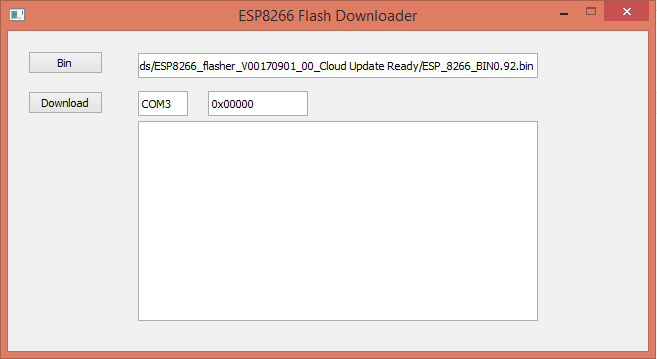 |
| Once everything is filled as needed, click Download. |
The firmware update process begins. If you forgot to start the firmware download tool as an administrator, it will fail and will create a log file in the same directory with the following content:
Exception in thread Thread-1:Traceback (most recent call last):File “threading.pyo”, line 810, in __bootstrap_innerFile “esp8266_flasher.py”, line 19, in runFile “downloader.pyo”, line 54, in __init__File “serialserialwin32.pyo”, line 38, in __init__File “serialserialutil.pyo”, line 282, in __init__File “serialserialwin32.pyo”, line 66, in openSerialException: could not open port ‘COM3’: WindowsError(5, ‘Access is denied.’)
The same error happens if there is another program using the same COM port.
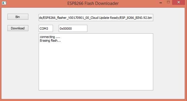 |
| Progress just started. |
If everything goes fine, you’ll see something like this on the screen:
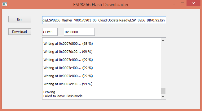 |
| After about one minute, the update is done. |
There is an error displayed at the very end of the process, which doesn’t seem to affect operation afterwards, so just ignore it. To wrap up the procedure there are a few more steps to do:
- Power down the ESP8266 module.
- Disconnect GPIO0 from GND
- Power on the ESP8266 module.
Ready, the ESP8266 is now upgraded to the new firmware. It’s time to test if it solved the problems I had earlier.
First steps – redux
When I powered up the module I only received gibberish in Putty. This was because I left the connection speed on 9600kbs. This new firmware defaults to 115200kbs, so it needs to be changed in Putty:
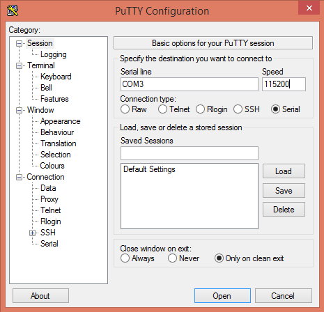 |
| Only the COM port and speed needs adjusting. |
Once I made this change, at the next power cycle of the ESP8266 I was welcome by this friendly message:
ready
All the AT commands I tried at this stage worked perfectly. So I did the ultimate test of the module: set it up as a wifi station (as opposed to access point, which it is by default), connect to my home wifi and access it (ping) from my main PC.
Everything went smoothly, this is how I did it:
Set the wireless mode to Station (1):
AT+CWMODE=1
Reset the module:
AT+RST
List access points:
AT+CWLAP
As a response, it will print out all the access points nearby. Something like this:
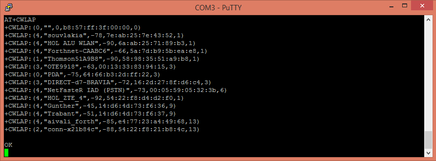
Join one of the access points:
AT+CWJAP=”ssid”,”password”
It should just say OK, if there was no issue while connecting.
We can also actively test if the connection was indeed successful:
AT+CIFSR – reports the IP address of the ESP8266
AT+CWJAP? – reports the access point’s name (SSID) the ESP8266 is connected to.
Also, in your access point’s configuration web page you can see if there is a new device connected:
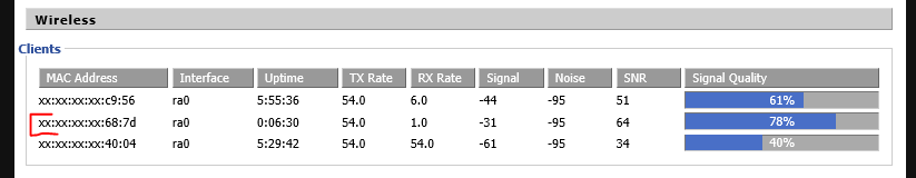 |
| I marked my new ESP8266 module with red. |
Final test, an actual connection to the device from another PC on my network:
In a Command prompt type:
ping [IP address reported by the device – see above]
In my case the command looks like this:
ping 192.168.1.134
The result should be something like this:
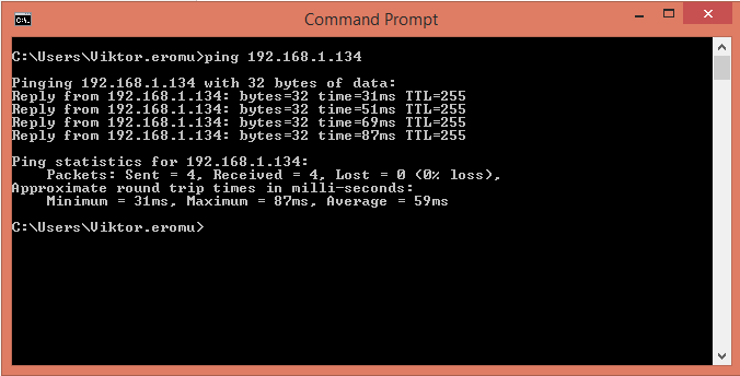 |
| Victory! |
Mission accomplished!
Next steps…
…include sending and receiving data to and from this module, and doing all kinds of cool stuff with it, but it will happen in a new article. Come back soon!
