
I must have thought there were not enough kinds/shapes/etc clocks in the world. Or maybe I thought: “I made one in the eighties, one about 10 years ago, so it is time for another one.” I’m not sure at this stage. What I do know is that I wanted to experiment with individually-addressable serial LEDs and building a clock that uses them was a great opportunity to do so. The general concept is nothing new, but I think I managed to add some cool new features that have not been done before – at least I haven’t found them on the internet.
Hardware
As light source for the clock, I chose individually-addressable LED modules. These modules have 3 LEDs (red, green and blue) and the control chip built into a single 5050 packaging. The clock has one such module for each minute of the hour. I purchased pre-built quarters of a circle that each contained 15 LED modules. In this arrangement, the LEDs are connected serially, so a micro-controller is able to control it using only one pin. Also, my work on the mechanical construction of the clock became a lot easier not having to mount and solder each LED individually. These LEDs are also know as NeoPixel LEDs:
NeoPixel is Adafruit’s brand of individually-addressable red-green-blue (RGB) LED. They are based on the WS2812 LED and WS2811 driver, where the WS2811 is integrated into the LED, for reduced footprint.
Wikipedia
Adafruit has a whole section dedicated to the use of NeoPixel LEDs. The page contains a lot of useful information, including best practices, on using these LEDs. It is a highly recommended reading for all before making their first NeoPixel design.
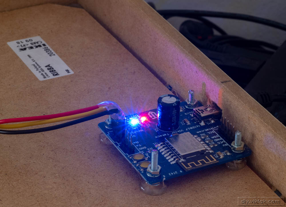
The LEDs, however, need an external micro-controller to control them. My choice of micro for this project was the ESP8266 based ESP-12F. I have used this SoC in several projects in the past. With its built-in web server (to allow the user to change settings) it’s perfect for a project like this where there are not buttons/switches on the final product.
I also designed a custom PCB for the clock. Well, not really for this clock…. Since every time I have PCBs made, the minimum number of PCBs I receive for a particular project is around 10, which means I have a lot of extra PCB. As it happens, I had a few copies of a PCB created for another project which I could re-use in this project without modification.
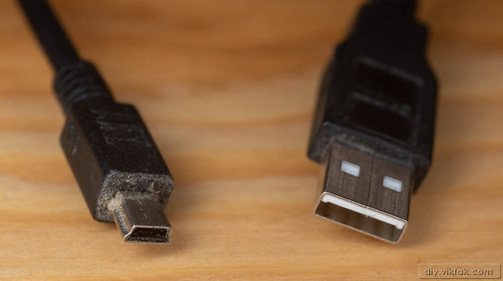
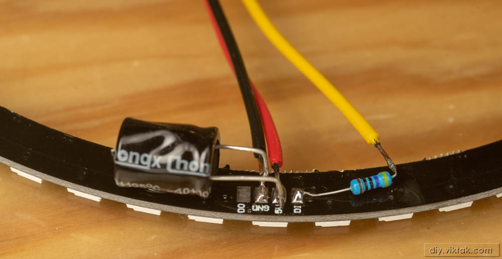
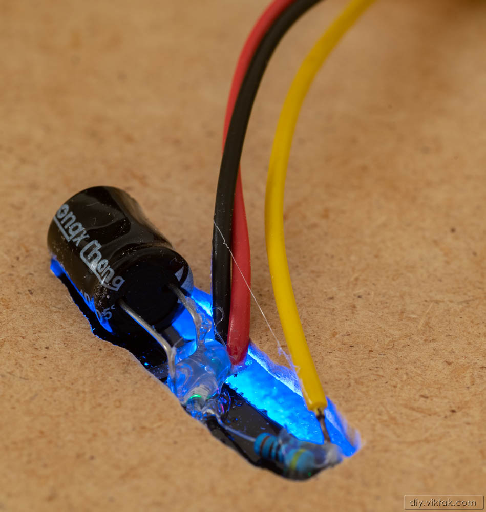
The clock operates from a single, generic 5V supply which can be produced by any mobile phone charger and is accepted via a USB Mini-B socket. Onboard is a 3.3V LDR to supply the micro with 3.3V. The LEDs are powered directly from the 5V. Important: To ensure proper working of the serial LEDs a 1000uF capacitor must be connected as close to the LEDs as possible. I soldered this capacitor directly on the back of the LED circle, not on the PCB.
Fun factoid of the day 🙂
In the early 2000s when USB Mini-B connectors were found on all consumer electronics, I accumulated many (i.e. tens of) USB Mini-B cables. I kept them all thinking it might be good for something in the future. Then a couple of years ago, when these cables had not been used for years as they were replaced by cables of newer and newer standards (of which I am also rapidly building a stockpile), I started to use them to power my electronic projects. The reason is that its corresponding USB socket is small enough but still relatively easy to solder. At this stage I have built so many, that I am now out of USB Mini-B cables. I never thought this would one day be possible!
Firmware
I have written the firmware for this clock in C++ in the Arduino framework using Microsoft’s Visual Studio Code with PlatformIO. The code is a modified version of my own framework (ActoSenso) for the ESP8266, like several projects of mine before. So far, it has the following features:
- Features common to all ActoSenso devices
- On power-on, it automatically connects to the last used WiFi network if any. If connection cannot be made, it creates its own WiFi network so that users can connect to it anyway and make changes (for example to connect to a new WiFi network).
- Streamlined web interface for displaying and changing user adjustable settings.
- Event logging via serial port AND using MQTT connected to a central server (I use my home automation server for this).
- Automatic synchronization of system time from a predefined NTP server at regular intervals.
- Features developed uniquely for this clock
- Shows hours, minutes and seconds of the current time
- User selectable seconds, i.e. the clock should show seconds as well, or just hours and minutes.
- Setting number of trailing LEDs for each unit of time (hours/minutes/seconds): When selected, a number of trailing LEDs are also lit up behind the main marker, with descending illumination, creating a nice, trailing effect.
- User selectable 5 minute marks can make reading the clock more easy
- Reverse clock: when this setting is active, the clock works anti-clockwise. It is for advanced users only! 🙂
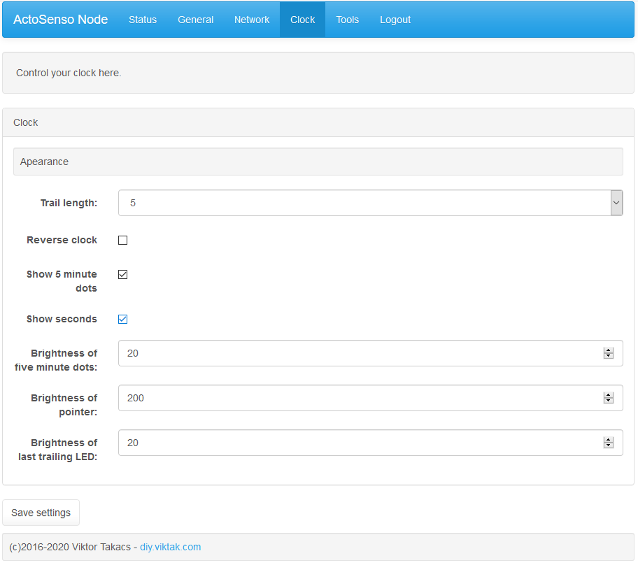
The firmware is open source and is available in my GitHub repository.
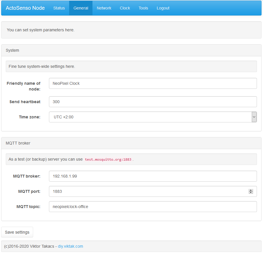
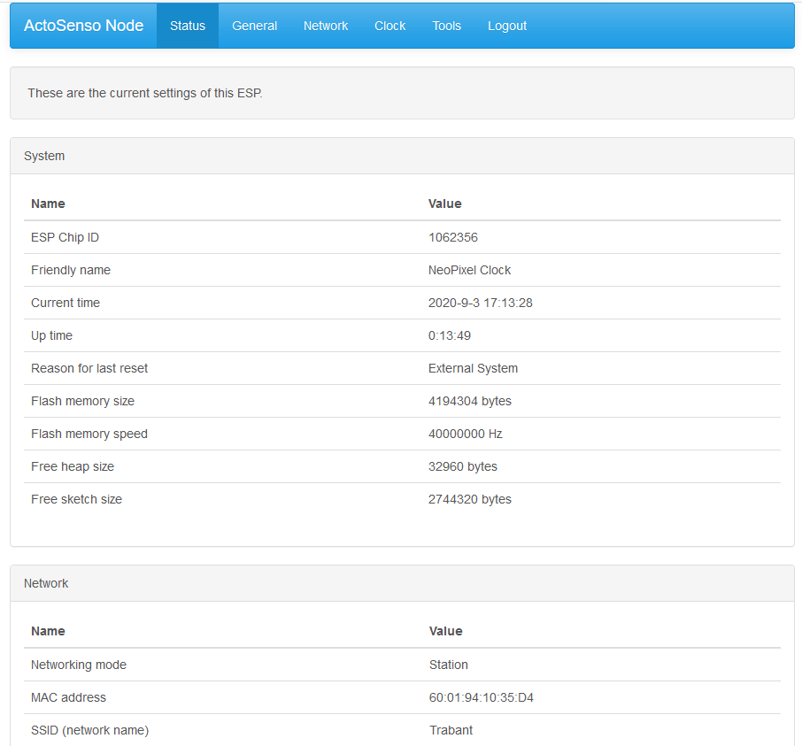
A few sample screenshots of the “settings pages”:
Mechanical construction
This is the part of most of my projects that is the most difficult for me, especially, because this time I used some materials (mirror foil) and methods that were new to me.
I picked a cheap IKEA picture from as the housing for the clock, mainly because I had one lying around. These are the steps I did to prepare it for the clock:
- Prepare glass (that came with the frame)
- I cleaned the front glass as thoroughly as I could with a soap solution.
- I applied mirror foil on the glass on one side.
- Prepare back panel (that came with the frame)
- Measured, double measured, then triple measured the location of the LED ring and marked it on the back panel.
- Cut holes in the back panel for the cables and capacitor (remember that extra capacitor for the LEDs?).
- Secured the LED ring to the back panel using a few dots of hot clue.
- Drilled/cut a hole on the frame at the center of the bottom side for the USB connector.
- Secured the custom PCB to the back of the back panel using some hot glue. To align the USB socket with the hole on the bottom side of the frame (previous step) I used screws and nuts in a reverse position, then chopped off the excess parts of the screws.
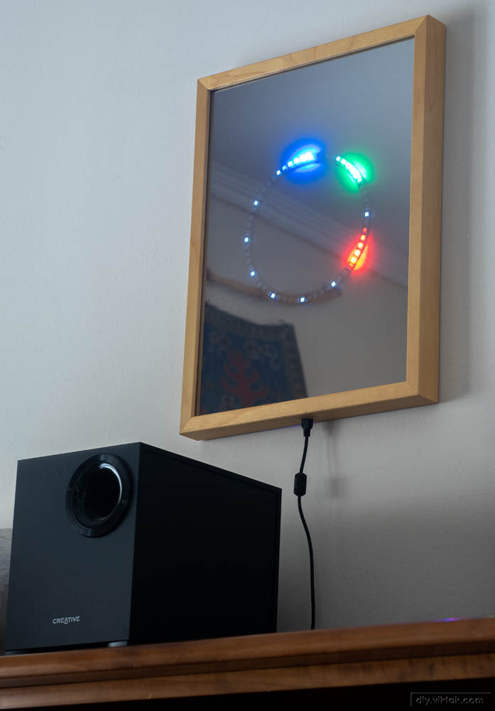
All ready!
Result:
Conclusion
As far as the mechanical construction of the clock goes, I am not 100% happy with the results I got, but there is a learning curve for everything and now I know how/what I will do differently the next time I build something similar.
With the rest of the clock I’m quite happy. Decades ago I saw a mechanical clock in a friend’s house that was running anti-clockwise and I managed to build it in this design. I haven’t seen it anywhere else since, so I consider it as a novelty feature – but don’t take it too seriously! 🙂 It was a fun project to learn to use individually-addressable serial LEDs.

Pingback: Yet Another RGB Clock – Viktor’s DIY Blog