Introduction
This digital clock displays the time in binary format. Binary clock s have become very popular recently, many hobbyists create their own version of it and they are even available commercially. To decode the time you need to be familiar with the binary number system and have to decode it pretty fast, before the time changes :-).
Note: If you want to build this circuit and need help, please let me know – I can provide you with any or all the parts for this project, including a preprogrammed PIC.
Hardware
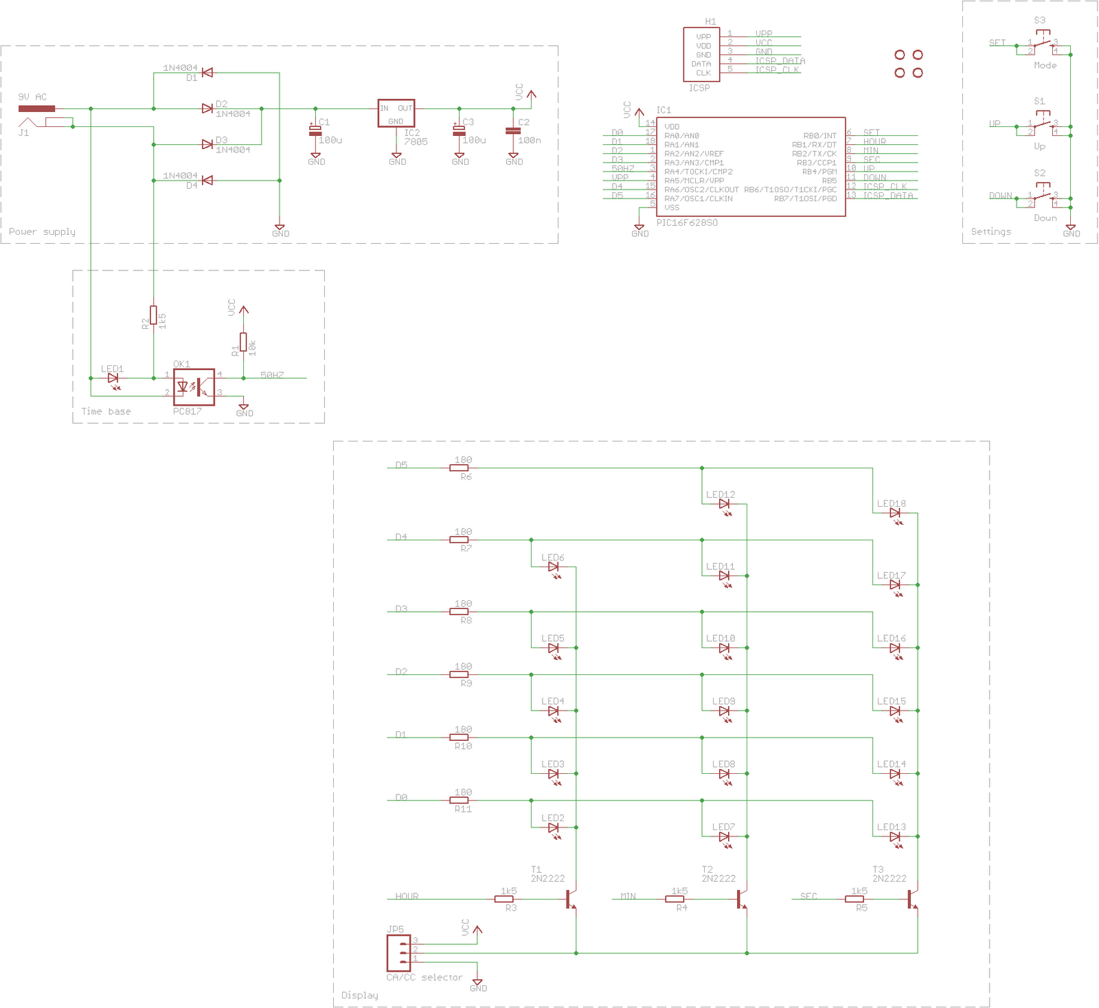
At the heart of the circuit is a PIC 16F628A microcontroller. I picked this microcontroller because I had this already at home and it also had all the peripherals and I/O pins I needed.
 |
| I actually used up all the pins of the PIC for this project. |
The power is supplied by an old power supply which is some leftover power brick from an old electronic device. It can be any power supply (within reason) that provides at least 5-6 V AC. Alternating current is essential for this project as the PIC micro takes the time base for clock operation from the 50 Hz of the power supply. An optocoupler provides galvanic protection for the PIC. The AC is then directed by a Graetz-bridge, then a 7805 stabilizer IC makes sure the PIC and the rest of the circuit is provided by the necessary 5V. Since the power consumption is very low, it doesn’t need any heatsink.
The display part of the circuit is made up of 17 LEDs organized in 3 columns: 5-6-6 for hours-minutes-seconds. It displays time in 24 hour format, so the highest value the hour ever displays is 23 (5 bit is enough, for minutes and seconds this highest value is 59 (6 bit value). Since the microcontroler has limited number of I/O pins the display LEDs are multiplexed: at any one time only LEDs in one column are lit up. To overcome the current sourcing limitation of the PIC micro I used some NPN transistors I had already.
I used all the three remaining I/O pins of the microcontroller as buttons to set up the time.
The circuit also contains a 5 pin ICSP header for easy development.
 |
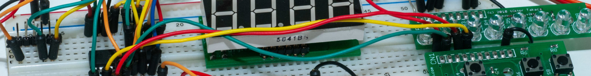
| The circuit is easily built on a breadboard within an hour using my LED strips and a button strip. |
Software
The firmware for the PIC 16F628A was written in assembly. This is my first project to use interrupts. A good learning experience!
I do not publish the source code here, but if you are interested, please send me an e-mail and I will gladly send you the code.
Operation
Button UP increments the minutes by one. DOWN button decrements the minutes by one. If MODE button is pressed while any of the other buttons are used the hours will get incremented or decremented. If MODE button is pressed on its own the seconds are set to zero.
Assembly
I also designed a PCB for the circuit. The PCB was to fit the enclosure of an old/broken power supply. I managed to squeeze all the parts in this small rectangle using mostly SMT parts.
| Empty PCB… |
| … to fit this enclosure |
The first thing to do before assembly is to check if all the wires are intact on the board and no short circuits occur. Populating the board with all the parts doesn’t require any special skills, and is not very difficult if you take care to first mount the smallest parts and gradually move onto the bigger ones.
 |
| The fully populated board – I had to chop off some of the 7805 IC to fit in the enclosure. |
 |
| The fully populated board from the other side |
Possible future improvements
This clock, as it is at the moment, is quite punctual – it has been working on my desk for 4 month and, for some strange reason, every time I check it it is a bit fast or a bit late. Never more than a few seconds. On average it’s correct. 🙂 I don’t need to set the time all the time. In a future version I could add a Real Time Clock module to it to keep it running even in a power cut.

What software did you use for your PCB design?
Thanks, great project!
Hi,
I used the free version of Eagle. I think it's great for the hobbyist. You can find it here: http://cadsoftusa.com/freeware.htm
Thanks for stopping by!
oh, I remember my school days 🙂
thanks,
(http://codedincantation.com/blog/)
That's the point! 🙂
please send me a mail with the source code. I am doing something like this for a school project. Thanks a lot
Mail: aditza90@yahoo.com
BTW Good job
Code sent in private mail.
Hello! Please send me if you can, hex code. I want to make my daughter such a clock in her room. Thank you!
PS: Congratulations on your achievement!
Mail: pbastiurica@gmail.com
Code sent in private mail.
Thank you very much!
This comment has been removed by the author.
hi !
pleas send me hex code and any things might help about this project
abdulelah252@gmail.com
Thanks alot
Code sent in private mail.
Thank you very much
Hello! Please send me if you can, hex code.
thank you very much…
ozgurkudis@gmail.com
Code sent in private mail.
Hi,
I am interested in making this clock, so please send me the hex code
silnangmarak@gmail.com
Thanks.
Code sent in private mail.