Introduction
This is an old school circuit – I made it (with the help of a friend) in 1987, when I first started out in digital electronics. At the time there were no PCs – or at least not for the average person in Hungary. So all the planning was done in paper. The proof is the following photo 🙂 :
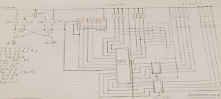 |
| No computers were harmed in creating this circuit 🙂 |
This circuit is an LED lightshow, or LED chaser. There is no microcontroller or microprocessor used in this circuit making it an easy entry to the world of digital electronics.
A short video demonstrating the features of this circuit:
Hardware
The clock/motor of this circuit is a simple astable multivibrator. It generates a 1-2 Hz clock pulse for the 7493 counter/divider. The output of the binray counter is fed into a 2716 or 2732 EPROM. This is a memory device that can be erased by exposing it to UV light and programmed by an EPROM programmer. At the moment I don’t have an EPROM programmer, so I am stuck with the programs I programmed when I originally made this circuit. Using a 2716 EPROM it can store 64 programs of 32 steps each – a 2732 EPROM would store twice as many programs, the two are PIN compatible. The output pins of the 2716/2732 cannot directly drive LEDs (or it would be borderline…) so I had to put in an inverter gate (7404 or 7406) which is designed to drive higher current that is suitable for LEDs.
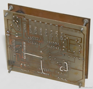
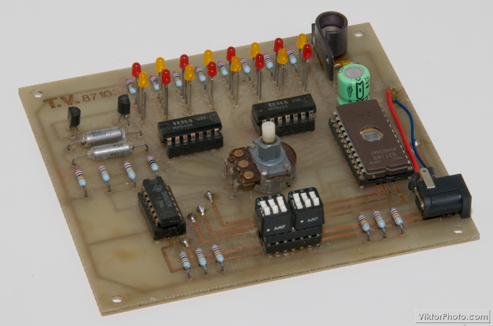
 |
| The circuit is made up of some TTL ICs and a few discrete components. |
The logic ICs are all TTL, the required 5V is produced with a transistor/zener diode/resistor combo. In the schematics I took the liberty to change this to a single 7805 stab IC alternative for simplicity.
Selecting the desired program is done by grounding one or more of the address lines of the EPROM. These lines are normally at TTL level 1 or high with a pull-up resistor.
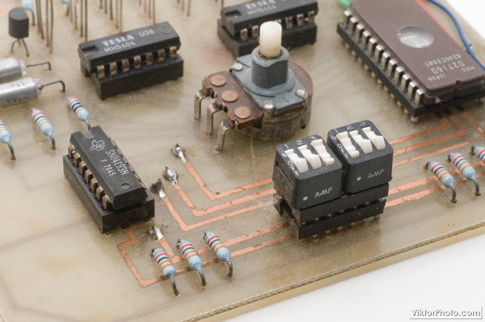
 |
| Close-up of the DIP switches and potentiometer |
The values displayed in the schematics are not critical for most parts. The speed of the lightshow is controlled by the potentiometer R5.
Since there is no microcontroller or microprocessor in this project there is not code to be written, although the patterns still need to be stored in the EPROM. I don’t have any program at hand anymore, and I am not planning to change what I already have in the EPROM for sentimental reasons….. (and I also don’t have an EPROM programmer any more…) However, it’s very easy to do if you want to do it yourself. You just start writing bytes in the EPROM one after the other. One program consists of 32 steps.
Let me show you an example:
Let’s say you want one LED to “move” back and forth.
The steps may look like this:
00000001
00000010
00000100
00001000
00010000
00100000
01000000
10000000
01000000
00100000
00010000
00001000
00000100
00000010
00000001
… and so on…
Building the circuit
There is not much to it – no SMT or other difficult parts in this circuit – the board can be populated in 20 minutes easily. Some care should be taken at design time to arrange the components on the board in a way that the LEDs, switches and pot are where you want them to be.
 |
| The fully populated board |
The board pictured above was done at home. Most wires could fit nicely on one side, although 5 or 6 straight wires had to go to the other side. You can see some corrections and extra cables and a connector added later. The white cables were design errors I had to correct after I populated the board and the board didn’t work. All the others I added just now to accomodate a “proper” connection to a power supply.
 |
| 4 white cables are to correct the mistakes at design time |
I mounted another piece of PCB, spray painted to black, to be the faceplate with 4 long screws to finish it off. The paint job originally was very good, but after twenty some years of being kicked around in our basement it doesn’t look very new any more…
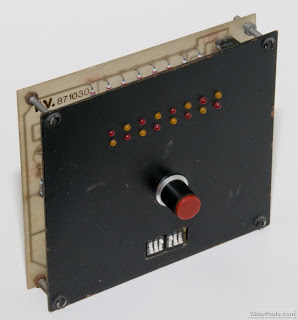 |
| The finished gadget – the black paint doesn’t shine as great as in the old days… |
Possible improvements
This is a very old project of mine using “old” technologies (EPROM, TTL ICs, …). All this could be improved, but I like it as it is. The only thing I might mention is that this circuit with minor modifications could be used to drive solid state relays instead of (or next to the) LEDs and then the lightshow would be with “real” lights!


Fantastic! I did my AS in the late 80's, so I am all too familiar with designing absurd systems with the 7400 series, and all the associated teething disasters mixing TTL and CMOS. POP! Grey smoke that smells of cat pee… I love it!
@Obsoe: It's nice to know I'm not the only one thinking back at the 80's with nostalgy 🙂 Thanks for calling in!
Wow!!!, some time ago I was thinking exactly in the same idea, but using an eprom pulled out from an old board, without modifing the stored codes. Have you tried this?
Best regards.
Diego
@Diego: No I haven't – I guess the result would be a "random" lightshow. It would be interesting though to discover any pattern in an actual piece of code.
Nice to see old school design, without microcontrolers
can you suggest any program that would fit and would definitely make it run? we just need it for our term project.. we need a programmable led lightshow,and this looks very interesting and easy to understand..can you please send me the schematic diagram and the PCB layout..a reply is very much appreciated..we just need to program it using our C++ or anything using the computer (laptop as a switch.) pls..hepl me pass my term project..
tnx and regards! godbless!
@Anonymous: You can find the schematics on the first photograph above – I'm afraid I don't have a digital copy of that at hand. At the time I made this circuit the PCB design was also done on a film not computer. But this circuit is very simple, I'm sure you can do it in an afternoon or so from start to finish yourself.
Also, there is no CPU in this project which means there is nothing to program in C++. The EPROM is programmable with the LED sequences outline above in the article.
I hope this takes you a bit closer to your project.
addtion to my comment, if i remove the EPROM and change it using only my computers C++ or any program compatible to it,is it possible and will it work?
@Anonymous: I'm not 100% what you are trying to accomplish: the EPROM on ly gives out a byte of info on its data lines when a certain address of it is selected.
If you simply want to create some PC programmable LED show, you can simply hook up a few LEDs directly to the parallel port of the PC.
Could you please tell the programming for the EPROM used for this circuit?
To program the EPROM you need an EPROM programmer for the EPROM you use in your project. You can find tons of suitable programmers on eBay.