Introduction
I have a few projects in mind for the near future which all have one thing in common – they all require remote controls to be operated. So I decided to experiment with remote controls a bit.
 |
| A small selection of my huge pile of never or a very long time ago used remote controls that are waiting to be repurposed. |
Selecting a transmitter
Since this is my first attempt to use IR as a communication channel I wanted to start out with a simple setup. This involved using an existing remote control so that I only have to deal with receiving and decoding IR messages. I already have a few IR remotes on my living room table and countless more in my junk pile…
After a bit of research on the internet I found Vishay’s TSOP series IR receiver modules which greatly reduce the complexity in receiving IR messages. According to the data sheet: “The TSOP312.., TSOP314.. series are miniaturized receivers for infrared remote control systems. A PIN diode and a preamplifier are assembled on a lead frame, the epoxy package acts as an IR filter.” I ordered a few of these decoders and when they arrived I immediately created the minimum test circuit to check out how they work.
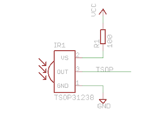 |
| I used this minimalistic circuit to visualize the waveforms. |
I used an oscilloscope to visualize the decoded pulses, but I also found some other solutions for hobbyists without a scope on other web sites. This page shows you how to use Microchip’s PicKit2 while this page uses a very simple circuit attached to the serial port of a PC to capture and visualize the output of the TSOP.
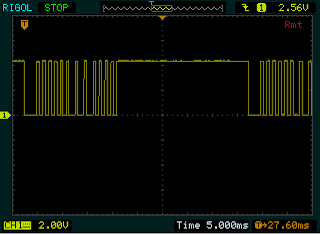
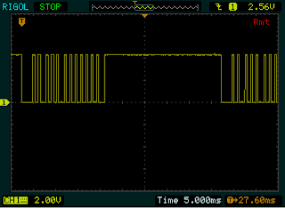
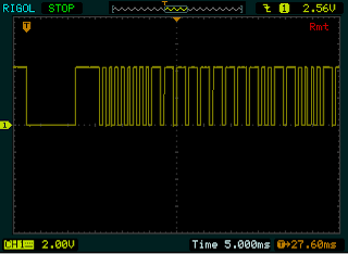
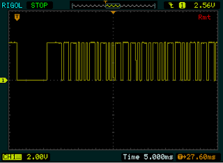
The following waveforms are from some of the different remote controls I tried:
Unfortunately, as you can see, no two remotes use the same standard. Eventually, I settled on using an IR remote of a Media Center that I had extra. This seems to use one of the simpler protocols of all the tested ones.
 |
| An old USB TV card kindly “donated” the chosen remote control |
This remote seems to use some standard very close to the NEC Infrared Transmission Protocol. The only difference I found is that the address bits are not repeated in inverse. It seems to me that this approach allows more devices to be addressed – at the cost of some loss off fault tolerance.
These are some sample messages I measured:
00010000 01100111 10101000 01010111 1
00010000 01100111 00101000 11010111 2
00010000 01100111 01101000 10010111 3
00010000 01100111 10000000 01111111 on/off
The above samples are enough to understand how the messages are structured: the first two octets are the address, the third octet is the command and the fourth octet is always the inverse of the command. In the last column I included the name of the button I pressed, it is not part of the message. For my purposes it doesn’t matter which way the octets are read, i.e. we can call the first octet 0x10 or 0x08, depending on if the LSB or the MSB is to the left.
Creating a receiver
To move on to something more useful I created another minimalistic circuit on the breadboard. To decode the commands I used a PIC micro, an 18F4550. Of course, this is overkill if you only want to decode the commands, but I had my reasons: First, I wanted to move up a step from the base line micros and thought this would be a good opportunity to do so, second, I will need this chip later on in the real project(s) for the IR receiver.
 |
| Schematics of the test circuit |
To display the commands I used a cheap, standard 2*16 LCD module. I also used a number of LEDs to make sure everything works as expected:
- One LED to indicate the circuit is powered up (probably the most important 🙂 ).
- One LED flashing at around 0.5Hz in the main cycle, to simulate normal program execution.
- One LED that lights up during the decoding of a single command.
Test application
{
unsigned int i, j, t1, t2;
if (INTCONbits.INT0IF){
LEDpin = 1; // Activity LED
t1 = MeasureLowTime();
t2 = MeasureHighTime();
if ( ( t1 + t2 ) > START_PULSE_LENGTH )
{
Address = 0x00;
NotAddress = 0x00;
Command = 0x00;
NotCommand = 0x00;
for (i = 0; i < 4; i++)
{
for(j = 0; j < 8; j++)
{
INTCONbits.T0IF = 0;
while(~TSOP)
{
if ( INTCONbits.T0IF )
break;
}
t2 = MeasureHighTime();
if ( t2 > ONE_PULSE_LENGTH )
{
switch (i)
{
case 0:
Address = Address | (0x01 << j);
break;
case 1:
NotAddress = NotAddress | (0x01 << j);
break;
case 2:
Command = Command | (0x01 << j);
break;
case 3:
NotCommand = NotCommand | (0x01 << j);
break;
}
}
}
}
if ( Command != ~NotCommand )
{
Address = 0x00;
Command = 0x00;
}
PrepareUI();
XLCD_CursorTo(1,4);
XLCD_WriteUChar(Address);
XLCD_CursorTo(1,13);
XLCD_WriteUChar(Command);
}
LEDpin = 0; // Activity LED
INTCONbits.INT0IF = 0;
}
}
This is a small video demonstrating the above:

