Introduction
Recently I have come across some smart LED light bulbs that came in different sizes, shapes, functionalities and manufacturers. One thing they share is that they all do their “smarts” over a WiFi connection for which you need to use a smartphone and one of the many apps that help you set up the bulb. Unfortunately, this poses the same serious privacy issue (as I have already shown in a previous article) as for the apps (and the light bulb) to work properly you not only have to be connected to the internet at all times, but you also have to provide sensitive personal data (like your home WiFi network’s name, password, your location, etc.) to a 3rd party you know nothing about.
This particular bulb is marketed as “LED Light Bulb” requiring the “Magic Home-Smart home” app for your smart phone.

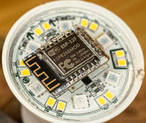
Many of the current bulbs on the market are based on the same chip, the ESP8266. These bulbs are very easy to “hack” and replace the firmware in them with the likes of my ActoSenso or the more widely known and used Tasmota. However, not all bulbs use the same chip. One of my bulbs turned out to have a Broadlink BL3336T-P WiFi module in it. This chip is not open source and not well documented (like the ESP8266 family), so anyone trying to write new firmware for it must first figure out what exactly the chip does and how exactly it does it. This is not an impossible task – some have managed to make great progress on figuring out the inner workings of it, but it is a slow, hit and miss process.
In this article I will show a different approach: I replaced the WiFi chip along with its PCB and other parts that drive the LEDs and designed a new, drop-in replacement based on the ESP8266 chip.
Preparations
After removing the white diffuser (the plastic “bulb” part) we can see the following building blocks of the smart bulb:
- LED panel: this contains all the LEDs and their current limiting resistors.
- Driver panel: this has the Broadlink WiFi controller and some other bits and pieces to drive the LEDs.
- Power supply (we can’t actually see this, but we know it is there, behind the LED panel 🙂 ): this provides the necessary power to operate the bulb.

I was lucky with this bulb on two accounts: First, the driver panel is a completely separate plugin to the rest of the bulb. This makes it easy to replace it with something else. Second, all the connections between the driver panel and the rest are labelled, so I didn’t have to figure out everything from scratch (doable, but it is easier/faster if I don’t have to). I still verified all the power and data lines, just in case.

WiFi module – top 
WiFi module – bottom
The circuit is very simple: the Broadlink chip drives the LED lines through a transistor each channel. This should be easy enough to reproduce with an ESP8266 based design!
Surgery
I had an ESP-12F module at hand, which I had used successfully on several projects in the past, so I quickly whipped up the following circuit:

Building one of the channels separately on a breadboard helped to confirm that the design should work fully:


Once I confirmed that the design is good to go, I designed a PCB for it. The obvious constraint was the size: if I make it too big, then the PCB will block the light from the LEDs. If I make it too small, I won’t be able to solder it. I borrowed the original design: the WiFi chip on the top, and everything else on the other side. All parts are surface mount to fit the size.
I ended up with a PCB design that is similar size of the original. I even had room for test points for reset and serial programming!

The new board is smaller (shorter) than the actual ESP-12F module. I chose white silk screen this time to help keep as much light from the LEDs as possible. (These bulbs are not very bright to start with…)

This project was sponsored by PCBWay. You should also give them a try: While it is possible to make your PCBs at home, having an experienced professional fab house, like PCBWay, manufacture the PCBs for you you will get much better results.
All the PCBs I ordered from them came out great, on time. So why wait, give them a try! Clicking on the image on the left will even give you some extra discount!
After assembly, but before soldering it to the original header, for the first time programming I soldered a few short wires to the Vcc, Gnd, Rx, Tx, GPIO15 pins, and programmed the device with my own ActoSenso variant tailored for this particular purpose and powered it up for the first time.
Using a mobile phone, I connected to its access point, then set it up to connect to my home WiFi network. Once I verified that the WiFi part worked OK, I removed all the tiny wires and mounted the board to the header, its final location.

After powering it up, I entered the configuration pages, set up the way I wanted it to work and was happy to see that everything worked as expected.
Results
Now I have a smart bulb that does exactly what I want, doesn’t need internet and I don’t have to trust any third parties with my personal information to switch on the light at home.
To change settings or use any features, I can visit its built-in web pages (like a router’s admin pages), or I can hook it up with any home automation system, like Home Assistant, OpenHAB or my own ActoSenso.
Sample configuration pages from ActoSenso:

Status page 
Program selection page 
Slowly changing program properties page


Any reason why GPIO0 isn’t pulled up ? And why is the ADC connected to ground ?
GPIO0 is pulled up internally.
ADC is grounded out of habit: when not used, grounding it reduces noise in/around the chip.
Thanks for sharing your much needed project with us. I HATE literally every single “smart” bulb that I have tried. ALL of them have major issues, and all of them require access to my network, and all of them send and receive data from people I don’t know (ie the manufacturer)’s servers. I was considering doing something similar, but never set the time aside to actually do all the research, etc. THANK YOU for sharing the fruits of your labor.
Question, – Is WLED something I could do on a setup like this, or do you prefer the Actosense? Assembling the PC board you have on PCBWay – how much is entailed in that whole thing? just soldering the ESP8266? Do you think using an ESP32 might be a better option or are the solder points different ?
Lot of questions, which is great! 🙂 Let me try to answer all of them:
1. Sure, you can use WLED. ActoSenso is just my own home brewed framework for similar projects. This saves me a lot of development effort and makes all my projects work along the same principles -> easier for the wife to learn :))). In general you can use any firmware that’s out there or one you write yourself. However, when using something different than mine, you may have to modify the PCB to make it work (or modify the code to match the PCB).
2. Assembling consist of soldering EACH component you see in the schematics on the PCB.
3. You can also use an ESP32 to accomplish the same goals, but you need to re-design the circuit (no, ESP8266 and ESP32 are not THAT interchangeable), AND you need to port the firmware too (again, the ESP8266 and ESP32 are not code compatible). I used the ESP8266 in this project, because ESP32 is overkill for it.
I hope I answered all your quesitons, but if you still have questions, feel free to ask them here!
Nice projekt. Just got two of the same bulbs and have the same problem.
I would like to repeat what you did, but I am not very fit in microeletronics. Do you have a link to the PCB board. I would just get the ESP-12F from Aliexpress. Soldering is not a problem.
Thanks!
You can order a PCB at this link: https://www.pcbway.com/project/shareproject/Broadlink_Smart_Bulb_Conversion_to_Open_Source.html
Thanks! How did you connect the ESP to the FTDI for flashing. Vcc, Gnd, Rx, Tx are clear, but what about GPIO15? I thought GPIO0 to ground for flashmode. I am new to this stuff.
Thanks!
“I ended up with a PCB design that is similar size of the original. I even had room for test points for reset and serial programming!” SJ1 and SJ2 are the test pins respectively, I am referring to, and I could temporarily short them with a set of tweezers. Or you can temporarily solder a small wire to them.
Have a look at the schematics above, it may help you better understand how it works.
What size did you use for resistor and capacitor? 1206 or 0805?
All the resistors are 0805, the capacitor is 1206.
Thanks for this I was about to do the same idea when I found yours saved me lots of time and effort have the boards in my pcbway cart now
Which firmware did you use ? Tasmota is my usual go to for esp projects if you did the same to you have the template used ?
In this particular case I am using my own firmware (https://github.com/viktak/fws_v2 ), but of course, one can use anything else (open source!), like Tasmota.