
Introduction
With the recent launch of Windows 11 Microsoft also made having a hardware TPM module mandatory. Although this technology is not new (it was introduced in Windows 10 and Windows Server 2016), now, that most people can’t upgrade to Windows 11, it will (slowly) become mainstream. (My personal opinion on it is that is probably a step in the right direction, but Microsoft could have handled mandating it better..)
Several months ago, when I heard about this new requirement, I checked how much this upgrade for me would cost. At the time prices for a TPM2.0 module for my motherboard (Gigabyte AORUS GAMING 3) started at around €150, which is not much less then, but definitely comparable with, the price of the motherboard itself. Not prepared to pay that much for a “free” Windows 11 upgrade, I started to look into if and how I could create the same thing on my own.
Research, things I learnt
During the research for this module I learnt that these modules are not identical for each motherboard brand and model, which makes it somewhat difficult for the average user to buy the correct one. I found that the modules required for the various motherboards vary in only two parameters:
- The interface between the motherboard and the TPM2.0 module. Some motherboards communicate with the TPM2.0 module via SPI, some use I2C, other LPC. My motherboard uses the LPC interface.
- The physical socket/connector. There are many variations on this, my motherboard has a 6 * 2 pin header on it.
I also found a manufacturer of such TPM chips, Infineon. They have a whole range of chips catering for the older, TPM1.2 standard and the current, TPM2.0 standard, in all the different communications interface combinations.
My motherboard requires a chip with the LPC interface, so I ordered a few SLB9665 chips on eBay. It turns out that in small quantities I can buy this chip for around €3 apiece. Also, according to the datasheet, it needs almost no external parts to make it work with the motherboard.
Schematics and Circuit board
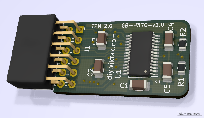
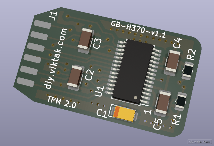
I designed the schematics using the Typical Application Circuit in the datasheet with minor changes also based on the recommendations in the datasheet. It contains little more than the SLB9665 chip and the connector to plug the whole thing in the motherboard:
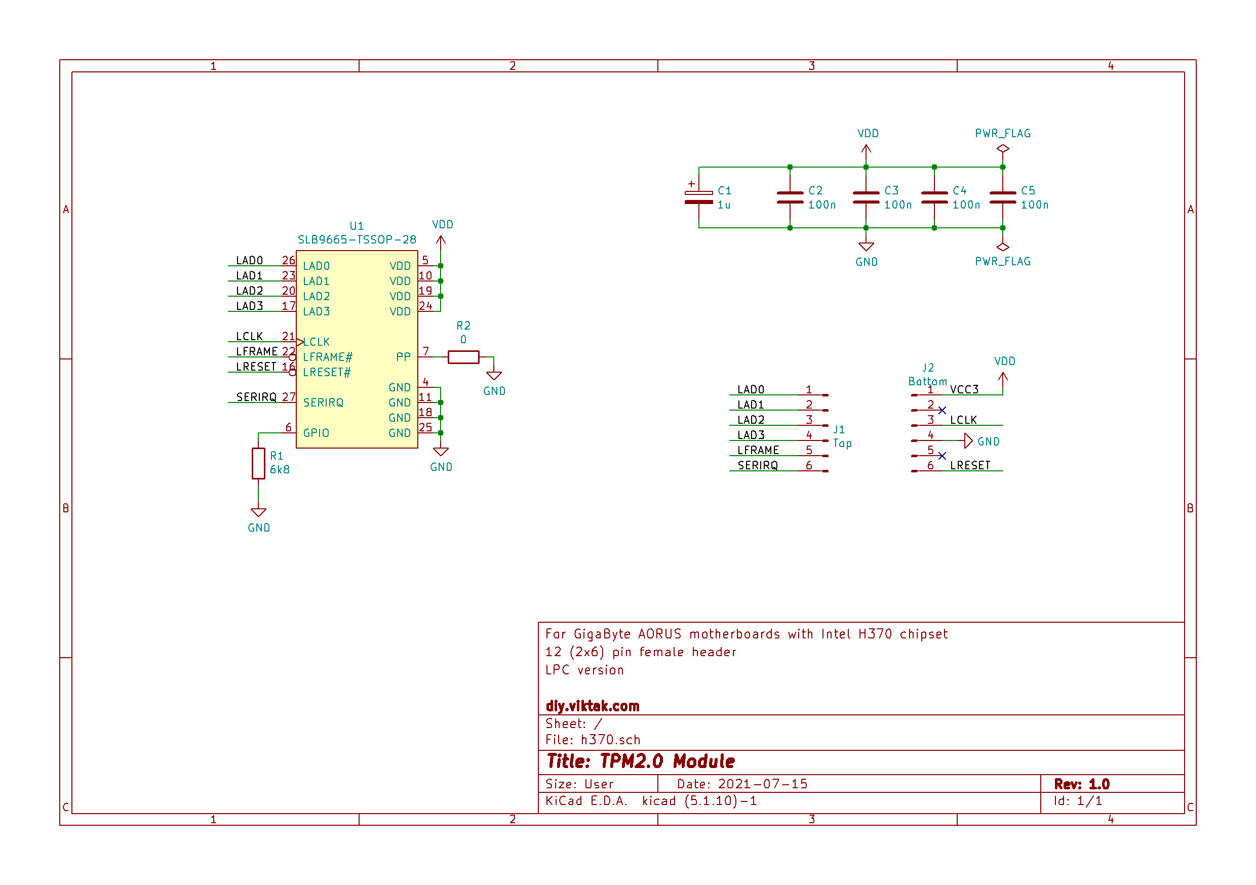
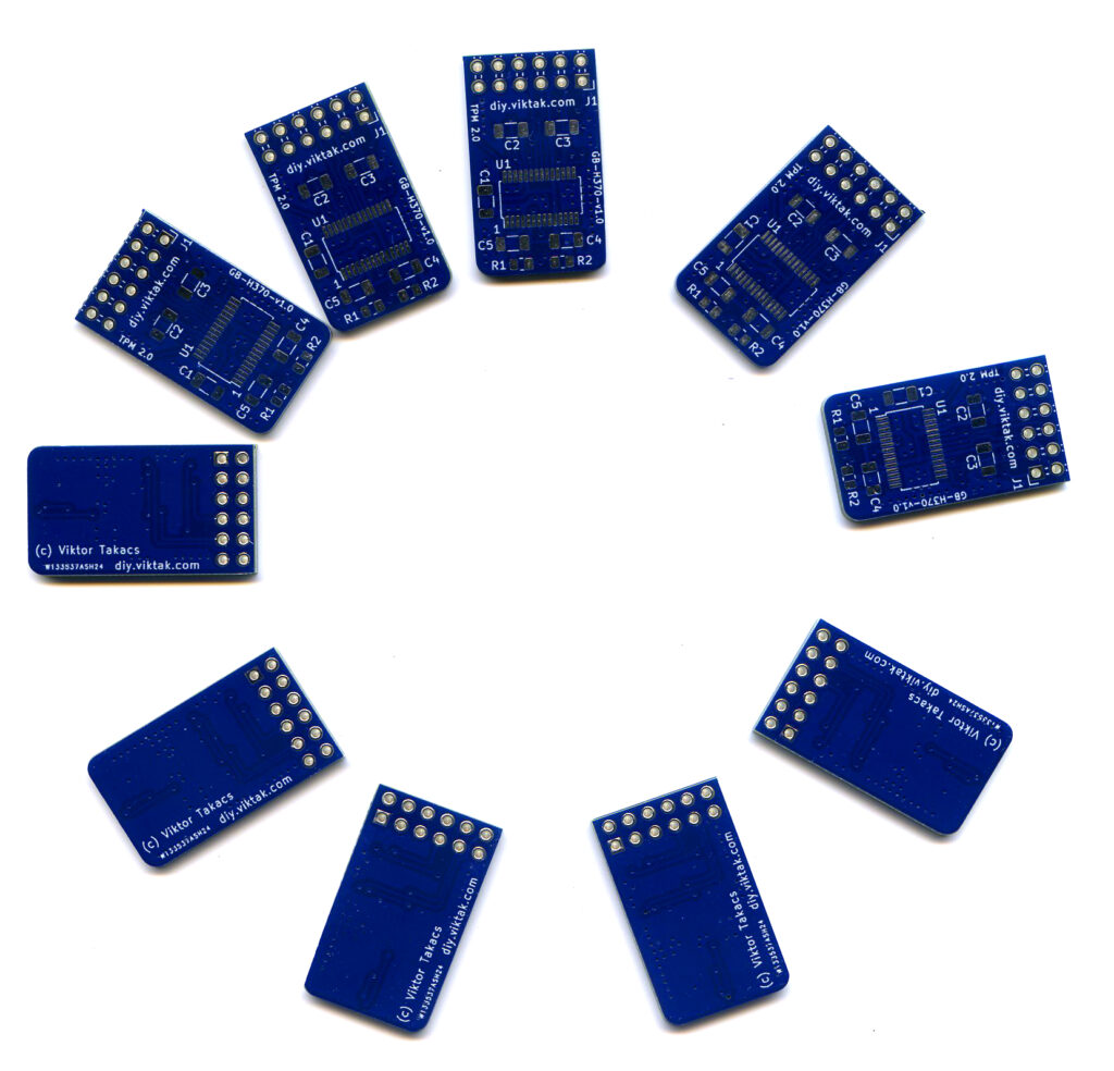
All this fit nicely on a tiny PCB of 28mm*16.3mm:
A word about the sponsor of this PCB

Although it would be possible to make this PCB at home, I opted for a professionally made one by PCBWay. I have used them in the past with success and I knew that the PCBs I order would turn out great. The ordering process was smooth, and within 24 hours of ordering, the finished PCBs were handed over to the post. The PCBs arrived in perfect condition, with plenty of protection around them. The soldering pads were all clean and soldering was a breeze, no cleaning of the PCBs first was necessary. And get this: I ordered 10 PCBs, but I got 21 in the box. Way to go, PCBWay! If you also want your own custom PCB professionally manufactured, click on the picture to the left and order your PCBs today!
Results and … surprise!
After populating the PCB I couldn’t wait to try it out. I double and triple checked all soldering points, tested the board for short circuit and when I was satisfied that no red lights were blinking in my head, I proceeded and plugged it in the motherboard. Or at least that’s what I had in mind. However, to my grief I realized, that the header on the motherboard had a 2.0 mm pitch and I designed my PCB with a 2.54mm pitch connector! I was so mad at myself…
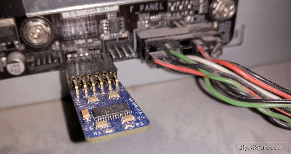
Luckily, I had a 2.0 mm pitch socket at home. Of course, it wouldn’t fit the 2.54mm pitch holes in the PCB. Still, with a bit of tinkering I was able to solder it to the board, using some tiny extension wires. The resulting piece of art is definitely not eye candy, but it did the job. I am writing these lines on a PC, that has my own (slightly ugly) TPM2.0 module and Windows 11 installed. All in all a success.
And this is how the final masterpiece looks connected to the motherboard. It’s been there for a while now, so it is dusty…:
Based on the above, TPM2.0 modules for various other brands/models can be created with minimal effort.
You can find the design files in my Github repo.

Nice… However, your motherboard supports 8th and 9th gen CPU’s. Those have a software TPM that works nicely with Windows 11… You just need to enable it on the motherboard. But it is a nice solution 🙂
Hmmm, I did not know that. Now that you mentioned it, I looked in the BIOS settings, but I didn’t find anything related to it. Also, its official spec doesn’t mention it: https://www.gigabyte.com/Motherboard/H370-AORUS-GAMING-3-WIFI-rev-10/sp#sp=
Can you point me to a resource that shows exactly where/how to set it up?
Sure…
https://www.oneninespace.com/enable-tpm-2-gigabyte-motherboard/
Thank you, Kurt!
It also only works if you have UEFI boot setup and a newer spec SATA drive, without those it won’t work despite having a TPM module, which is why I’ve stuck with Windows 10. Horrid standard, poorly executed!
Yeah, I feel your pain… One more option to try is using Rufus to create the installation media: https://github.com/pbatard/rufus
Its latest version allows you to “disable” the TPM and secure boot requirements. I have used it to upgrade some very old machines that were nowhere near meeting the minimum requirements for Windows 11, and they are now all updated to Windows 11, they never complain.
Nice!!! My MB doesn’t even have a TPM header… Unfortunately, my MB is very pricey to replace…
Check out Rufus, see my comment above!
How re programing SLB9665 fw convert 2 to 0 ?
Is there any chance to mount this TPM 2.0 chip to a PCIe card instead? SPI interface is not always available and current manufacturers are not offering PCIe interface TPM modules. Thanks!
I’m afraid I do not know. The port I used is a dedicated TPM port that is available on all modern motherboards, so I don’t even see the point using a PCI slot for this. I think it is not enough to have an SPI interface, the motherboard/CPU needs to support it too. When it does, it has a TPM port as well.
Can slb9665 be connected via USB?
Nope, not in itself. Have a look at its datasheet: https://www.infineon.com/assets/row/public/documents/30/49/infineon-data-sheet-slb9665-2.0-rev1.2-ds-en.pdf?fileId=5546d462689a790c016929d1d3054feb