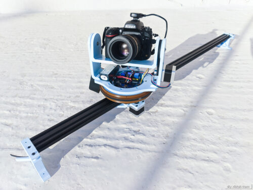
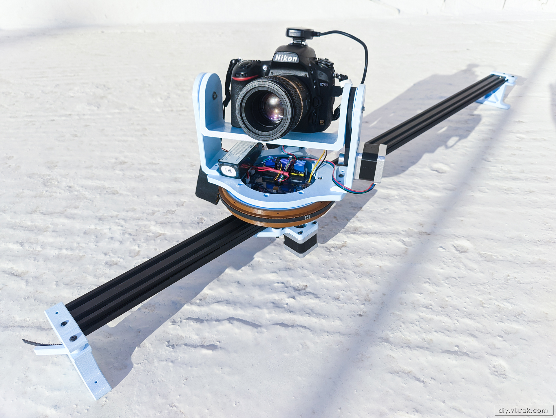
For a long time now I have been longing for a sliding platform for my video camera to take some smooth scrolling panning videos. Also, I have long wished to take proper panoramic images with my SLR. I have had some success using a tripod, but the process was a bit cumbersome and, if you ask me, it was begging for automation. After looking at the ridiculously priced commercially available camera dollies, pan/tilt heads I looked into making one on my own. As it turns out, I’m not the first one with this idea, quite a few have done similar devices before me. So at the end I didn’t have to reinvent the wheel, just had to steal borrow some ideas from existing open source projects, to create my own 3-axis camera mount. I was inspired and influenced by many designs, but the one that was the closest to the one I had imagined is isaac879’s DIY 3-Axis Camera Slider.
In the following I will describe the full build in detail:
Electronics
Mechanics
Firmware
Example shots
Making your own
Hardware
Electronics
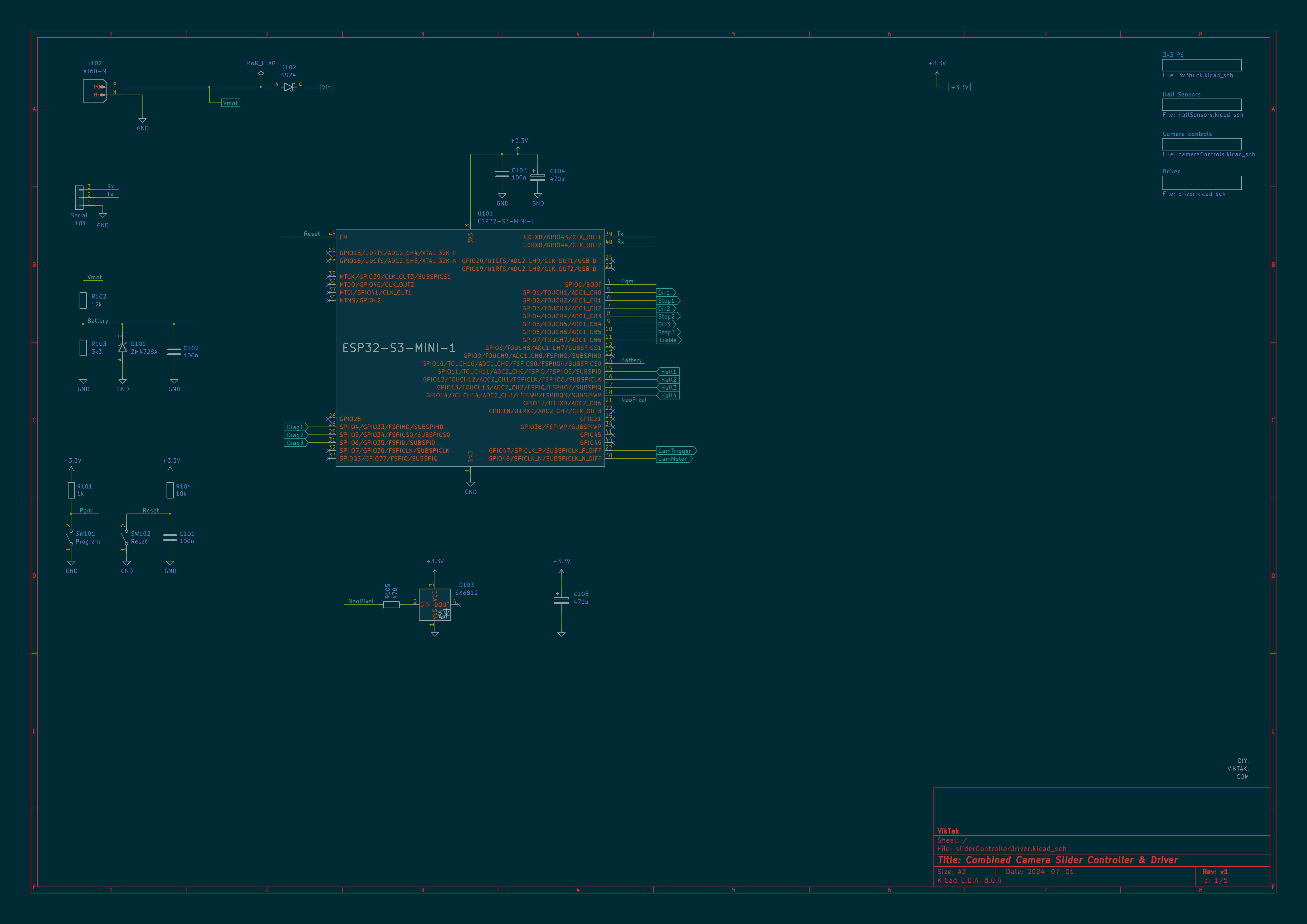
As can be seen in the above schematics, at the core of the operations is an ESP32-S3 microcontroller. This microcontroller is fast and powerful enough for this project, with GPIOs for various peripherals and many to spare. In fact it is a fairly basic circuit with only a few bells and whistles:
There is reverse polarity protection in form of a diode – this is not too efficient, and probably can be skipped as the power cable has a polarized connector (XT60) on it which makes it pretty much impossible to plug the battery in a reverse order.
I also included a NeoPixel LED for status information. Although the SK6812 LEDs are supposed to operate off a 5V power rail, my tests showed that this one LED can do away with 3.3V with no problem.
As I intend to use the camera slider mostly away from home, I have to use a battery to power the device. I needed a battery, that can provide high current to the motors plus some extra for the controlling logic. This sounds awful lot like a battery commonly used from drones. So I did some research on LiPo batteries, and settled on the Ovonic Air 3S 2200MAh battery. This battery has not only an XT60 connector that I can easily attach to my controller board, but it also comes with a built in charging cable for balanced charging, making charging it a breeze. As its name suggests, the battery consist of 3 cells in serial, giving a total of 11.1V nominal voltage, a bit more when it is fully charged.
The battery directly drives the stepper motors. This means, that when it is fully charged, the circuit gets about 12V. To provide the rest of the circuit with 3.3V, I use an MP2370 based buck converter, which steps down the voltage to the desired 3.3V value:
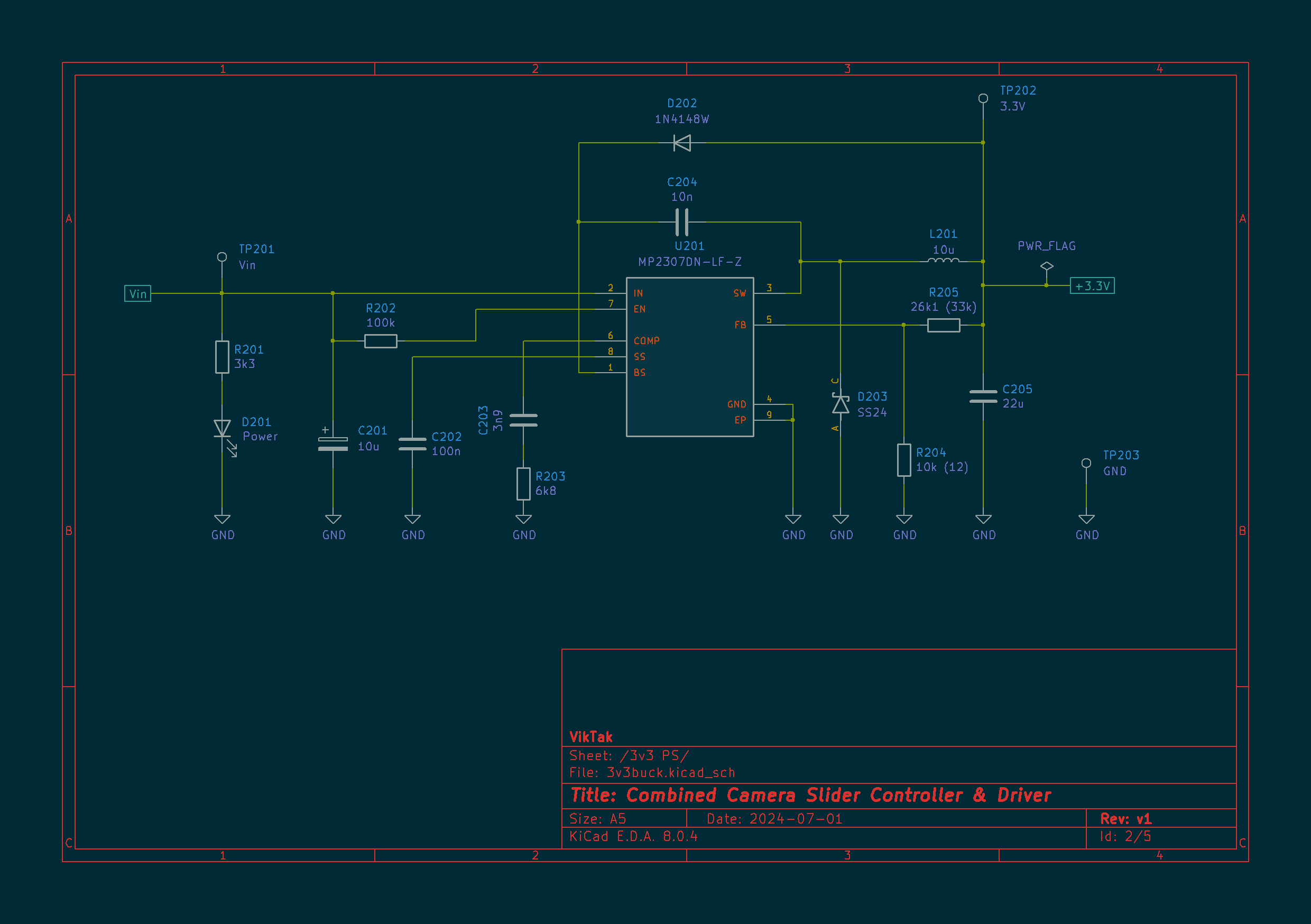
LiPo batteries get damaged when used under their minimum voltage levels. So I also added a simple resistor divider with a 3.3 Zener diode to monitor the voltage of the battery using one of the ADCs of the micro controller. According to the battery’s manufacturer, this minimum voltage level for my battery is 3.3V. So I designed the battery monitory function in a way that when the total voltage (of the 3 cells) is at 10V (3.33V per cell) it gives me a low battery warning, but the slider operates normally. However, when the total voltage level drops below 9.5V (3.2V per cell), the device gives a visual indication of it (Status LED turns to constant red) and also disables all of the motors. When this happens, the slider cannot be used for taking pictures any more, it is time to replace the battery!
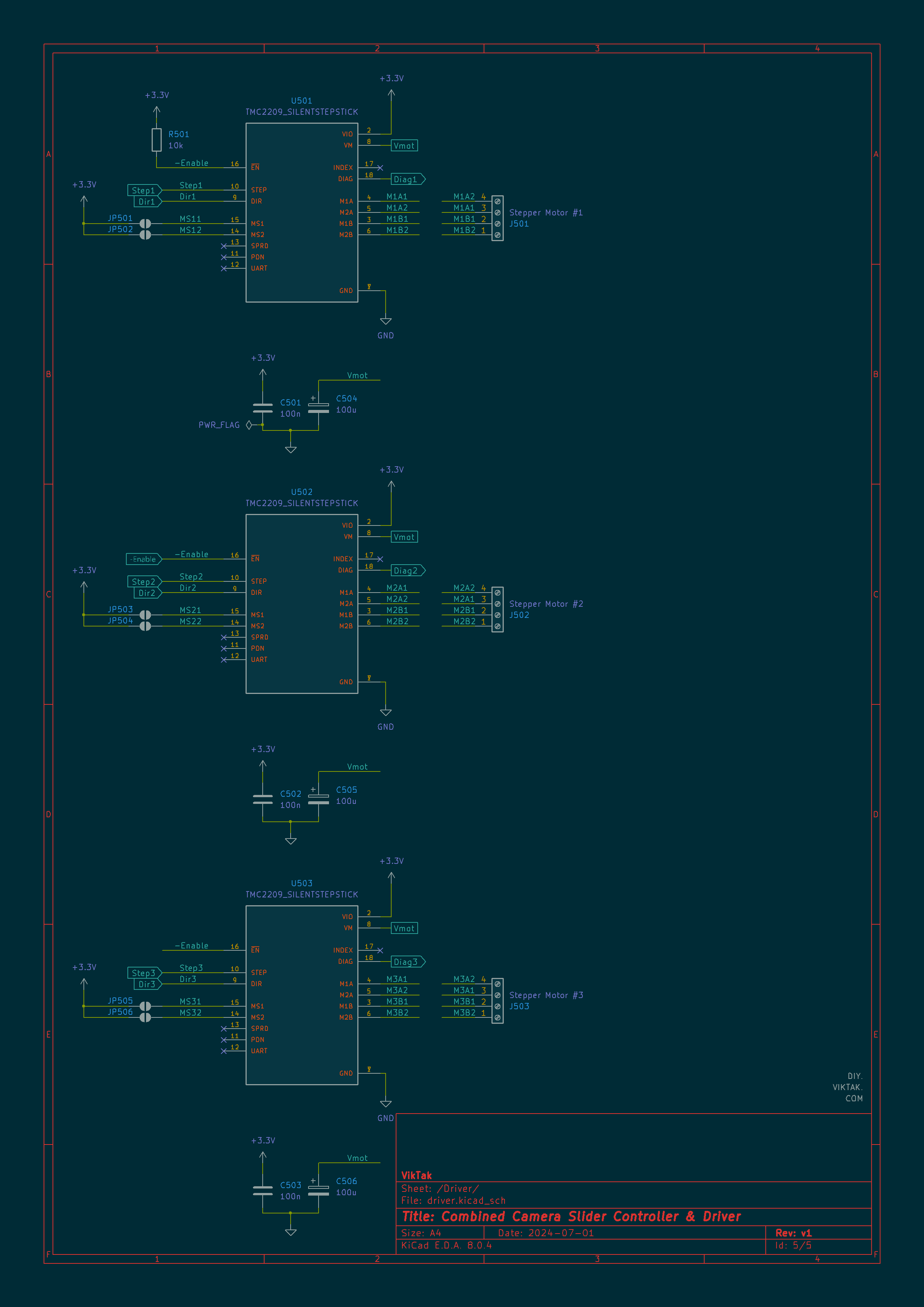
The movement of the 3 axis is driven by NEMA17 bipolar stepper motors. These stepper motors are a good balance between size, strength and price. I did not, however, reinvent the wheel, and used off the shelf stepper motor driver modules to drive them. At first, I picked Allegro’s A4988, which worked just fine. Since this was my first project using stepper motors, I thought that the gentle humming noise coming from the steppers was a necessary side effect of using stepper motors. I even liked that sound too! But when one day an accidental short rendered one of the A4988 modules useless I had to get new ones. As I always like experimenting with new stuff, I decided to get different drivers, this time a couple of TMC2208s and TMC2209s. What a difference it made – the steppers now run almost completely silent!
To be able to repeatable movements on all three axis, I needed a way for the firmware to figure out the position of the stepper motors. At first I experimented with micro switches, but they didn’t give me a consistent result. So at the end I added four hall sensors to the circuit: 2 for detecting either end of the slider, and one each to the tilt and pan directions:
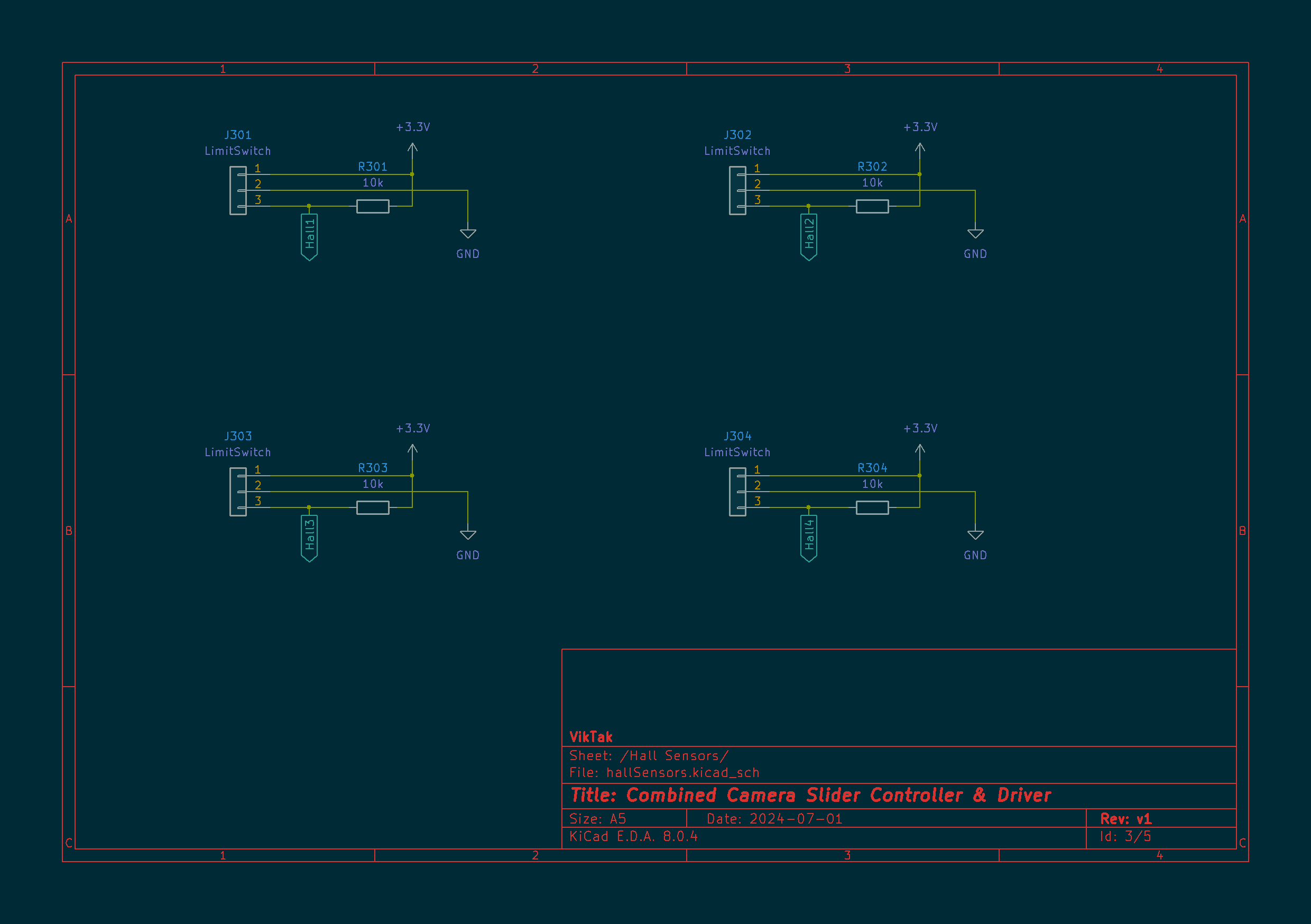
I used OH3144 hall sensors, because I had them already at home. Again, the datasheet claims that it needs at least 4.5V to operate, but they seem to be working just fine with a 3.3V power supply. So far none of the sensors I use have failed to detect what they should, so I think it is safe to keep them. Anyway, if I find out in the future that they do not work from 3.3V reliably, I can replace them with 3.3V alternatives.
Finally, I also added an optional connection to SLR cameras:

Most SLR cameras (and many others) have remote triggering feature. This usually manifests in a 3 pin connector on the camera that comes with a cable to connect to it. On the other end of the camera, usually, there is a button that works similar to the cameras’ trigger button: push it half way, it starts metering, push it all the way down, it takes the picture. Behind the scenes, all the fancy button at the other end of the cable does is shorts one or the other wire to the third one. This operation is very simple to exploit for my purposes: an opto-coupler can accomplish the same function. In theory, you can do away without an opto-coupler and use a FET or something, but using an opto-coupler makes your circuit galvanically isolated from the camera. I probably don’t have to emphasize why it is a good idea to protect a camera worth hundreds or thousands or euros… I used the same trick back in the day when I created my lightning trigger and sound trigger for cameras. It works on scores of different camera models – even ones that do not have remote release cables, only an IR remote. I simply hooked up the opto-coupler outputs to the buttons on the IR remote!
I designed the circuit and the PCB in KiCAD. Here is a render of the PCB:
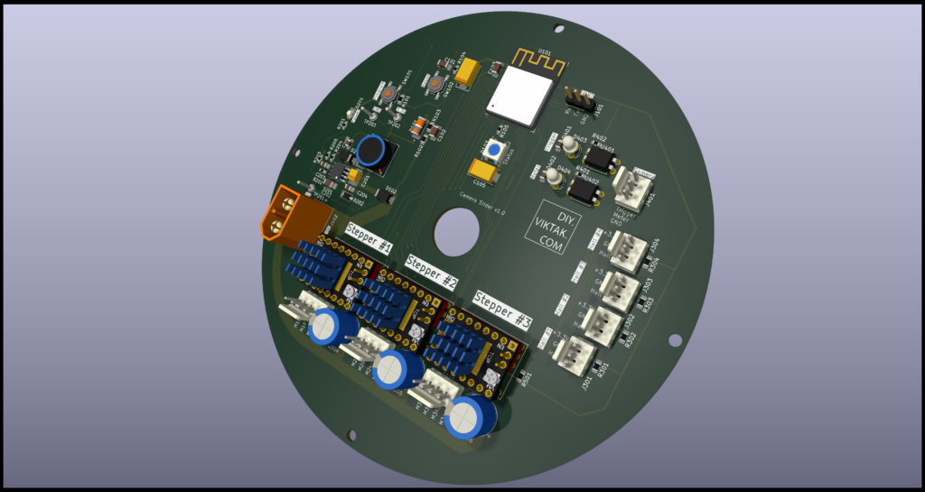

At this point I would like to thank PCBWay for sponsoring this project: Although it would be possible to make this PCB at home, I opted for a professionally made one by PCBWay. I have used them in the past with success and I knew that the PCBs I order would turn out great. This was no different this time: The ordering process was smooth, and within 24 hours of ordering, the finished PCBs were again handed over to the post. The PCBs arrived in perfect condition, with plenty of protection around them. The soldering pads were all clean and soldering was a breeze, no cleaning of the PCBs first was necessary. I also found out to my surprise, that even though I ordered 10 PCBs, I got 11 in the box. Awesome! If you also want your own 3-axis camera slider PCB professionally manufactured, click on the picture on the side and order your PCBs today!
Mechanics
The “base” of this slider is a 1200mm 2040 aluminium extrusion. I got the 1200mm long version because that was the largest I could find that could still be delivered via normal post from China. After deducting 40mm for the two stands and 120mm for the sliding head, it leaves around 1m net range, which should be enough for most projects while also not being too long to make transportation a nightmare. At a gross length of 1200 mm it is already borderline nightmare inconvenient…
Similarly, of all the different aluminium extrusions I went with the 2040 type as it is a good balance between stability/rigidity and weight. First I tried the simplest version, the 2020 profile, but it was too “bendy” at 1200mm. The 2040 profile is very sturdy, happily supporting its own weight, the pan/tilt contraption including the 3 stepper motors, and a SLR with lens, without any noticeable bending.
The pan/tilt head is mostly 3D printed. I used plain PLA for all parts, and they all seem to hold. One disadvantage of PLA is that when you drop the whole contraption, at least one part of it doesn’t survive the fall. (Ask me how I know this…) Luckily, the parts can be cheaply printed again.
I designed all the parts in FreeCAD, and they are all available for download to make your own pan/tilt head.
As I mentioned at the top of the article, I borrowed some ideas of others who came before me. My additions/changes are mostly in the areas of making the parts simpler, avoiding the use of 3D printed gears/threads, etc. For example, for transmission I use pulleys and timing belts. I found these are more reliable than two 3D printed plastic gears rolling on each other, as they often skip steps and wear out relatively quickly. With timing belts I have never had any such problems.
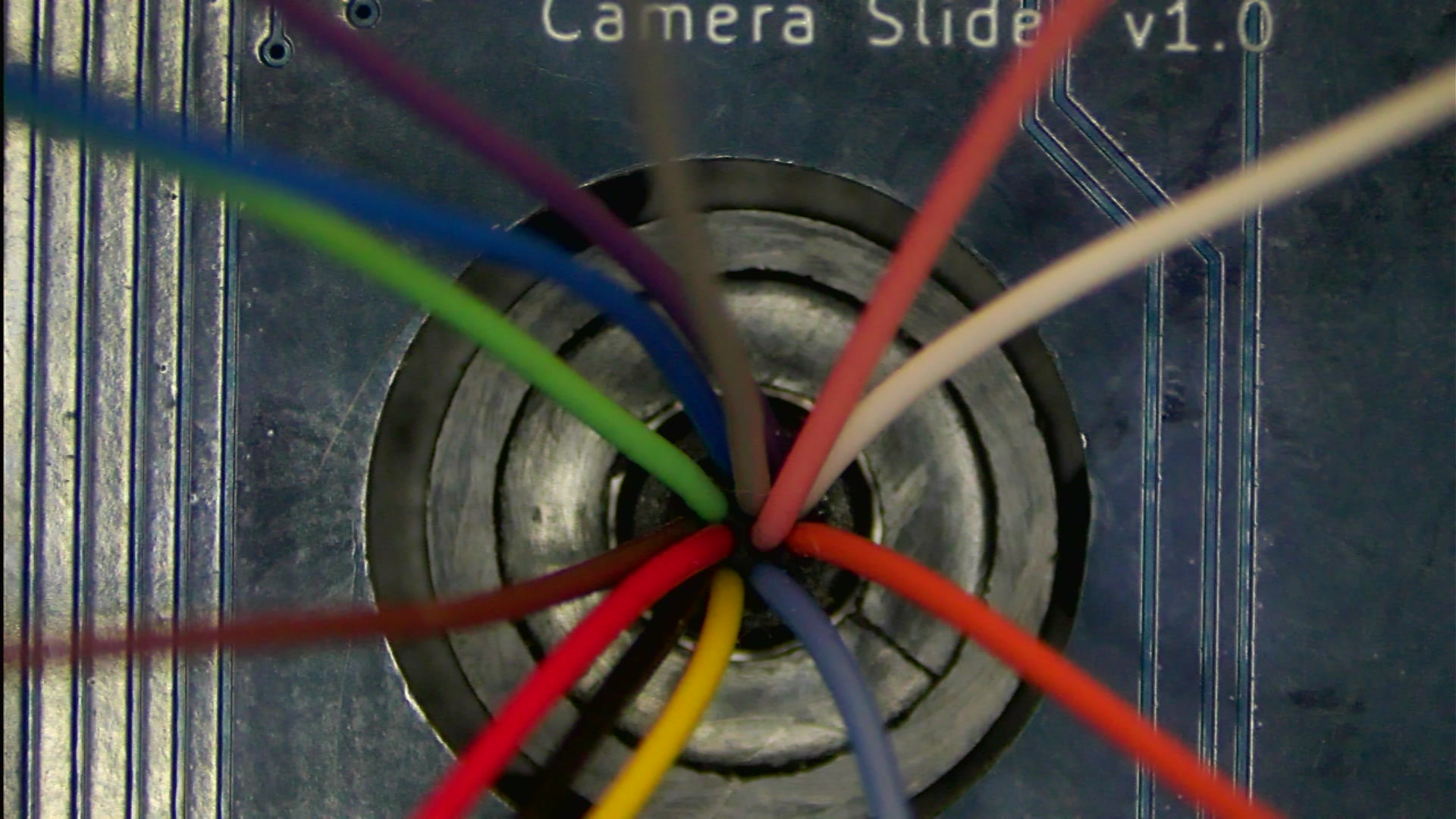
One point of interest is the 3D printed bearing that makes limitless panning possible. The rings of the bearing are 3D printed, and some steel balls are added to complete the bearing. Nevertheless, when I was done with this I noticed, that the bearing was not rotating smoothly enough: the tiny imperfection of the 3D printed parts caused the bearing to rotate not freely, but rather jerky. I tried to remedy this with loosening the tolerances, but the result was that the whole bearing got wobbly. Finally, I returned to tighter tolerances and added some grease. Of all the different greases I tried the “Titanium Metal Anti Melting Agent” turned out to be the best for the task: Apply just a tiny dot of grease at a random location in the ring, rotate the bearing in a few complete circles and voila! The bearing slides so smooth, it’s hard to believe it was not machined out of steel…

There are a number of power and other signal lines that go from the ever rotating pan/tilt head to the “static” parts of the slider:
- slider motor (4 wires)
- 3.3V
- GND
- Hall sensor signals (2 wires)
I found a slip ring on the market with proper mechanical parameters and a reasonable price tag. It has 12 channels, each rated for carrying up to 2A. According to the seller, the wires themselves are AWG30, which, according to several online sources like this, is probably just wishful thinking. The 3.3V, GND and hall sensor lines should be OK on this slip ring as they do not carry serious amounts of currents, but the stepper motor lines can (even if not continuously) carry up to 2A. So it was time to do some experiments with some chopped off bits of the actual wires: Using a power supply, I sent 2A down a wire and to my surprise, the 30AWG wire was unharmed, didn’t even get hot. This probably means the wires are not made of pure copper, probably some alloy, hence the increased current handling. Anyway, just to be on the safe side, I decided to use 2 wires/channels per stepper motor line. This way I am certain both the wires and the actual slip ring will last for a long time.
Firmware
I wrote the firmware in C++ using the Arduino framework using several open source libraries to accomplish the functions I wanted to implement. As there is no physical interface on the device to control it, all interactions are done through a web interface that is built into the firmware from another device that is connected via Wi-Fi.
Currently the main features are:
- Control via Wi-Fi from an external device (i.e. mobile phone, tablet)
- Both Station and Access Point modes are supported
- Built in web interface for settings and control
- Manual jog control
- Automated and repeatable timelapse recording
- Automated and repeatable panoramic photography
- Automated and repeatable 3 axis video recording
- Direct camera control (focus and trigger)
- Saving and restoring all photography/videography settings
- Battery monitoring – visual warning is given to the user when the battery is getting low
- Battery protection – visual warning plus motor operations disabled when the battery reaches critical level
This is the bare minimum I set out to do at the beginning. As my time allows, the features will expand to make it more user friendly and more useful in various other scenarios. For the time being it is in a very much usable state.
The user interface is pretty rudimentary at the moment, but it gets the job done. I will certainly polish it in the future.
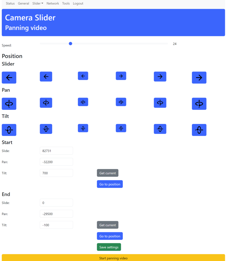
As there are several controls on the page, a phone with a large screen or a tablet/laptop is recommended for comfortable usage.
All source code is open source and is available in the project’s repository. All are welcome and encouraged to improve on it.
Example shots
Finally, here are some sample shots/footage I took with this automated 3-axis camera slider:
It takes a bit of practice to get the zoom/speed right although there is no right/wrong here, it all depends on your artistic approach.
Make your own 3-axis camera head!
If you like this camera head, I encourage you to build your own. Drop me a line in the comments or contact me some other way and I’ll be happy to assist you all the way!
Update 10, March 2025
This project won a Popular Design Prize at PCBWay’s 7th Project Design Contest! Thanks to all of you, who voted on this project of mine!

Hi, can you check your email to see if it’s in your spam folder (lepiko@hot.pl)
Tomasz, I have received all your e-mails and have replied to them. I even sent a simple test message to you yesterday. I don’t think the issue is on my side. Anyway, if you can’t see my messages, you can also write here. Or you can contact me on Signal or Telegram.
Hey Viktor, since i can’t find your email this will have to do.
Could you message me regarding this project? I’m looking for inspiration for a project and would like to make one of these to test.
Click on the little envelope icon in the top right to send me a mail! I can’t send you one as I have no idea who you are, what your e-mail address is…