One side effect of ordering PCBs from a professional fab house is that you always get more PCBs than you actually need. For example, when you place an order for a PCB prototype at PCBWay, you get at least 10 copies of the PCB, sometimes even more. In most cases, however, you rarely need more than one or two of them, the rest just sits in a drawer waiting for the rare event of you needing one or two more of them. I certainly have accumulated hundreds of PCBs that once were useful to me, but not any more. I always feel reluctant to throw them away as I keep thinking “I’m sure I will be able to use them for something in the future.” Over the years this even has happened a number of times. In this article I will show you how I was recently able to put a full project together using such old PCBs of mine. Granted, it is not the most complicated project of all times, it demonstrates a number of benefits this method has over creating a new design.
Recently, I needed to make a very simple clock with the following requirements:
- It has large numbers so even elderly people can read it without glasses from a distance (across a room)
- It should be set up once, no further user input needed for years (or ever)
- I also had a very tight deadline of a week or so (for personal reasons that are not relevant here)
Apparently, it is not possible to buy one ready – none of the commercially available clocks (I found) was just a clock.
Gathering parts that have been gathering dust for the last several years
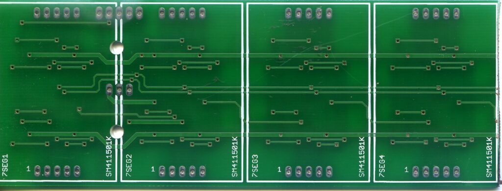
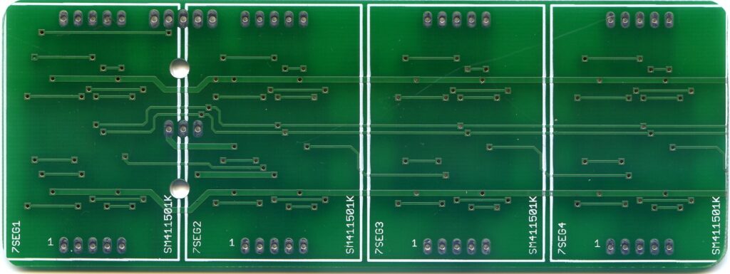
When I learnt about the first requirement, I immediately knew I would use some of those 1.8″ 7 segment displays, because they fit the bill and I already had a few left over from some old project of mine. Thinking on, I also remembered that a long time ago I made a breakout board for a bunch of these. When I dug into my old PCB drawer, I found them quickly:
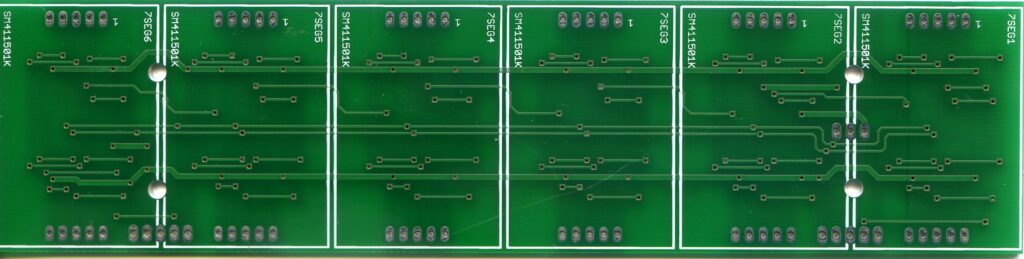
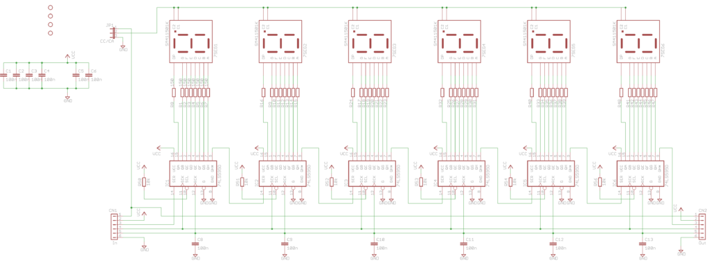
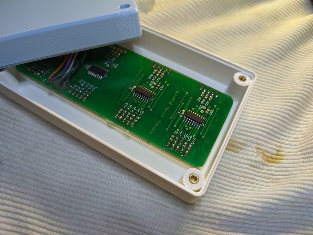
Well, this PCB is certainly one step in the right direction: it has at least 4 digits, can be configured to use either common anode or common cathode 7 segment displays and it contains the shift registers to drive the displays. The only problem with it is that it was designed for 6 digits. I could have left it as it was, and make a larger clock, but I really wanted to make the clock as small as possible. Luckily, the board was designed in a way that the components were laid out in a very “practical” way. Remember, the board uses daisy chained shift registers to drive the displays. This means that the chain can be cut between any 2 neighboring shift registers without breaking the functionality of the circuit. (Of course, the opposite is also true: if I wanted to build a display using, say, 12 digits, I could have simply added one more of these PCBs at the end of the first. If you have a look at the schematics/PCB you can clearly see that over 12 years ago I designed it keeping this expandability in mind.) So all I had to do was to cut the PCB to size: I made sure to keep the first 4 digits (counting from the entry point of the first shift register – IC1 on the schematics), then I cut the PCB with an angle grinder (I didn’t have a saw blade at hand…) right where the 4th 7 segment display ended. I filed the edges and made sure that the tracks cut did not cause any short:
After populating the PCB I had the display ready. To confirm that it was working as expected, I hooked it up with one of my ESP8266 development boards and wrote a simple program to test each segment of each digit. Great, time to move on to the circuit that would drive this display!
Again, I could have opted for the easy solution, and used that ESP8266 development board I just used for testing, but I didn’t like that it was much bigger than the display board which would have made the clock unnecessarily bulky. Luckily, I have done quite a few ESP8266 based projects in the past, all using an ESP-12F module. I quickly went through all those surplus PCBs and picked the smallest one that also had a USB socket (for power) I could find:
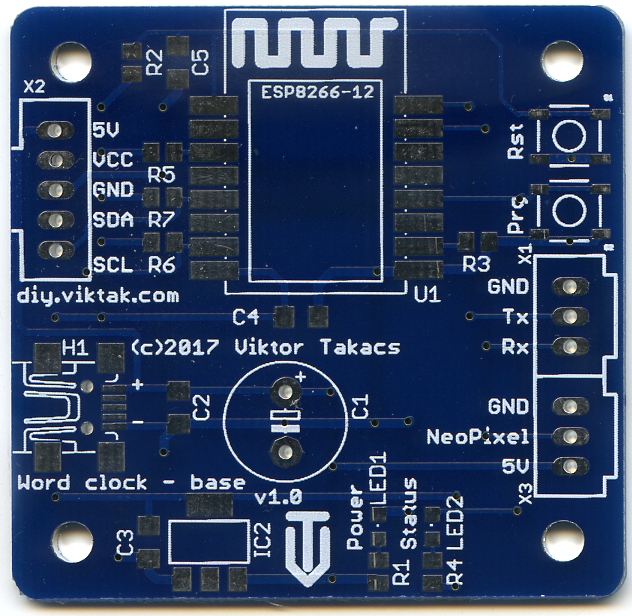
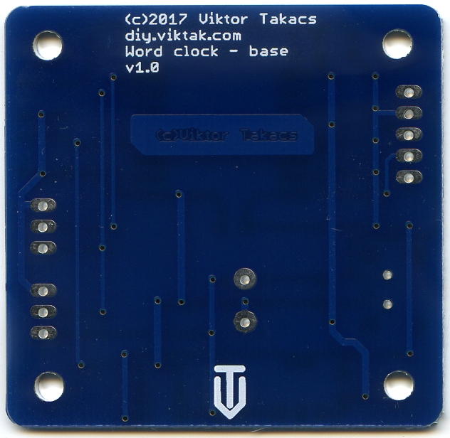
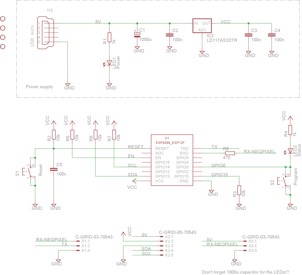
This PCB was used for one of the first iterations of my word clocks – it has an output for Neopixel LEDs as well as an I2C connector (neither of these are needed for the clock I am building now). But it has a USB Mini-B socket for power and the corresponding circuitry to power the ESP. The ESP module itself is easily “hackable” as it has huge, upwards facing pads that are very easy to solder small wires to.
Creating something new from the ashes of the old
To connect the two boards together for this particular application, I just needed to connect 6 lines between them:
- 3.3V power line to power the logic on the display board
- 5V power line to power the LEDs on the display board
- GND
- Serial data line
- Shift register clock
- Storage register clock
Once these connections were made I could start developing the code for the clock.
The firmware… is also recycled!
Well, mostly… Regular readers of this blog may recall that over the years working with the ESP family of chips I have developed a skeleton of firmware to base most if not all of my projects on. This project was no different: With most of the code reused I was able to write all the clock-specific parts in an hour or so.
The full source code is available in the project’s public repo.
Take cover!
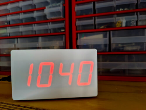
To cover up the build I designed an enclosure and printed it with my 3D printer:
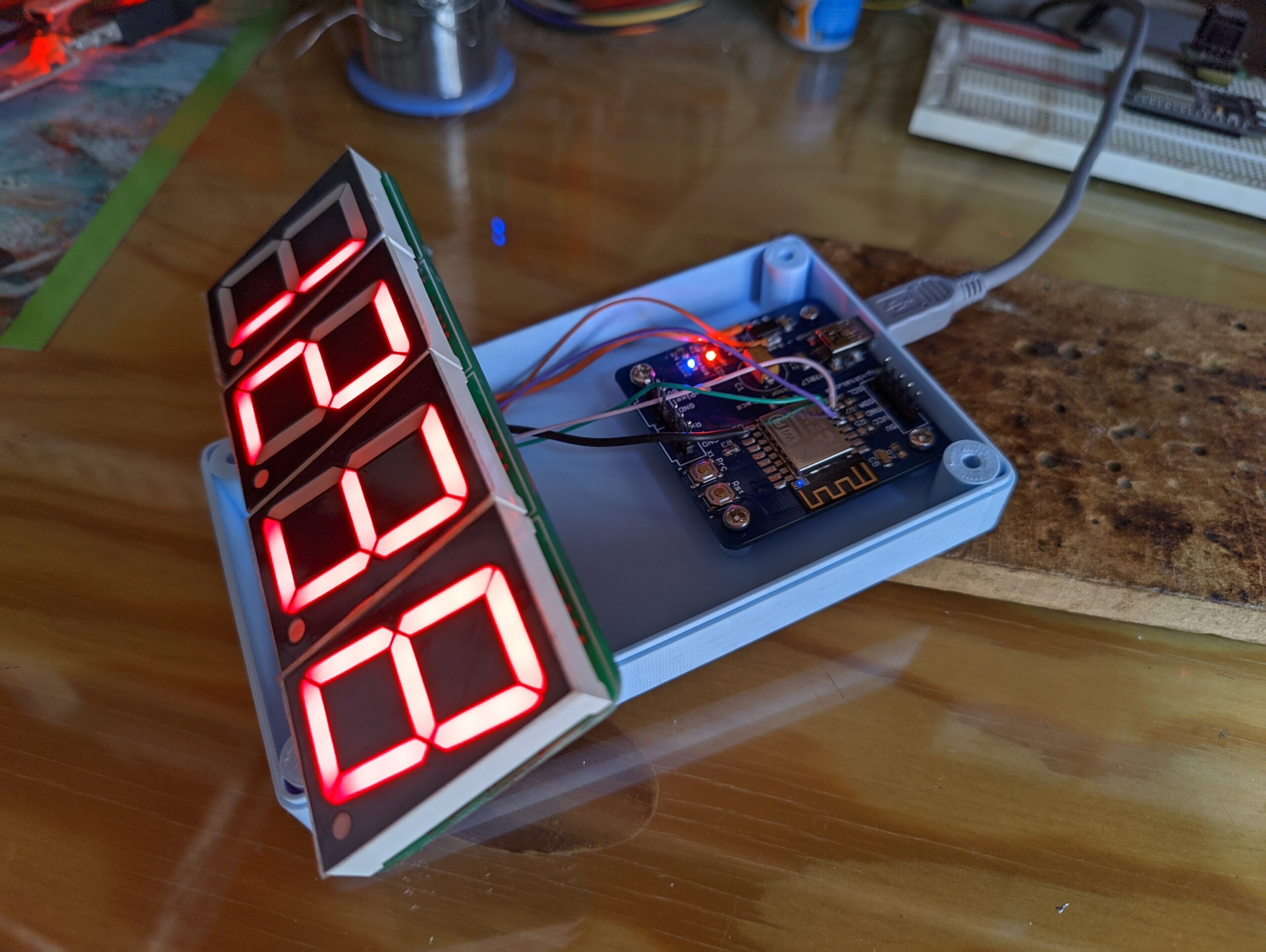
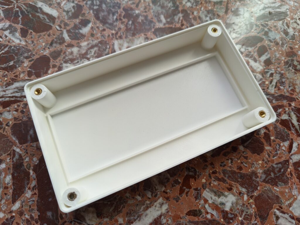
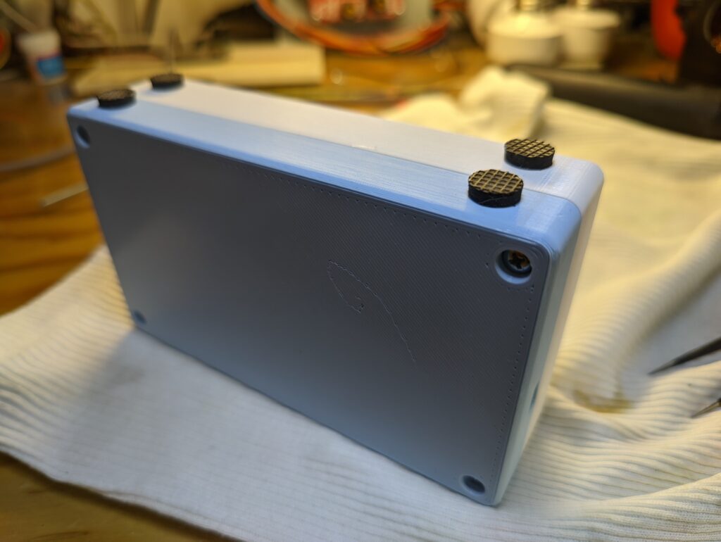
The front piece also acts as a diffuser for the LED segments, that are quite harsh otherwise (for my taste). It has a few mm high frame that holds the display in place using friction fit. To make sure it wouldn’t fall out I also added a couple of drops of hot glue. The front and back pieces are held together by screws in the 4 corners that screw in to brass inserts on the other end. Finally, I added a few rubber pads to the bottom side of the finished enclosure to make sure the clock and whatever furniture it will be placed on will not damage each other. (I always save these rubber stands from any old equipment I discard exactly for this purpose – I have a whole bunch of them at this stage.)
Conclusion
I hope I was able to demonstrate above that with a bit of creative thinking it is possible to make new projects that, while they are full projects in their own right, don’t have to go through the usual designing and sourcing of new parts, extended waiting periods for international post while generating waste every step of the way. To create this project from scratch would have taken me at least a month including a new PCB design and having it manufactured and shipped over. Instead, this whole project (except printing the 3D printed parts) was done in a single afternoon with time spared for a nice walk in the park. 🙂

I usually try to design my PCBs for a particular project in the most flexible way possible so that the same PCB could be used for something else as well in the future without going over the top and complicating the design too much. I think a good example for this was the 6 digit 7 segment development board I created over 12 years ago, or the main board for all these projects more recently.
And if you don’t have a project at hand to give those old PCBs a new life, you can also come up with one, like this PCB Smartphone Stand I created like a million years ago and still use on a daily basis…
