Introduction
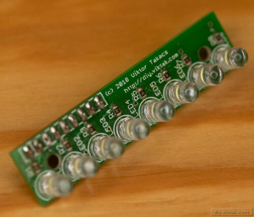
The aim of this simple project is to provide simple debugging capabilities to any digital circuit. It is nothing more than 8 LEDs on a piece of PCB with a pin header to connect easily to a test board or breadboard.
The circuit
The circuit doesn’t get any simpler than this:
Pin 1 of the header is the common. The above schematics shows the LEDs in a common cathode configuration, but it’s possible to reverse them making a common anode configuration if that is what a particular project demands. Also, the value of the resistors must be chosen according to the requirements of the circuit at hand. The shown values are just examples. Typically, the common pin (pin 1) can be a 0V and pins 2-9 can be connected to a microcontroller’s output pins.
The board
To save on manufacturing costs (which seems to be the highest for every circuit I have made so far) I used SMT resistors. The LEDs could also be SMT, but I wanted them to be big and I wanted them to shine.
Some more images
 |
| The empty PCB |
 |
|
You can see all the SMT resistors, all the LEDs and the header on the back.
|


Hi,
Nice blogs. One question. Are any of the PCB's published and I keep missing where the down link are?
Thanks
@johnnyfp:
I don't usually publish the PCB designs for two reasons: I always publish the schematics for my projects. PCBs are easy to recreate if you have the schematics (for people who have enough experience to build the circuit) and the PCB is greatly dependent on the parts you have available, so whatever design I make may not be useful for others anyway.
If one needs my help I will gladly help in any step of the process.