Introduction
The aim of this simple project is to provide simple button input to any digital circuit. I use it in conjunction with the LED strip in microcontroller projects on breadboards. It consists of 8 tactile switches (momentary pushbuttons). The circuit is complete with a pull-up resistor for each pushbutton. The included pin header allows easy connection to a test board or breadboard.
The circuit
 |
| The circuit is very simple |
Pin 10 of the header is the common one. Typically, the common pin (pin 10) can be a 0V, pin 1 is Vcc, and pins 2-9 can be connected to a microcontroller’s input pins.
The board
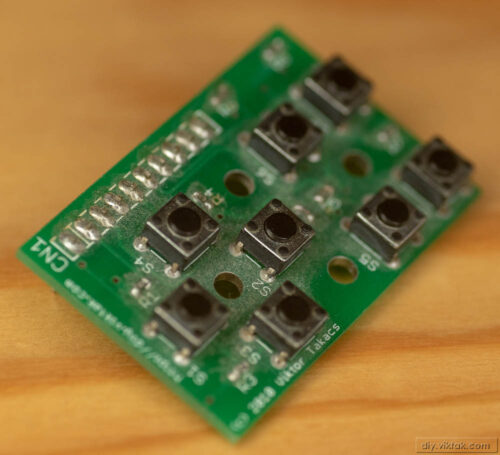
To save on manufacturing costs (which seems to be the highest for every circuit I have made so far) I used SMT resistors. I also arranged the buttons in a specific shape: rather than having them lined up one next to another, I made up the below shapes. This will help in various projects to easily distinguish between them. Now I have a button for Up, Down, Left, Right, and some extra ones on the right.
 |
| The empty PCB |
 |
| The fully populated PCB. You can see all the SMT resistors and buttons in a particular arrangement. |
