
The article below is a detailed description of a GPS and GSM based vehicle tracking solution I have created recently. Its major features:
- Real time location reports using an onboard GSM modem.
- Has a micro SD card socket for offline storage on a memory card – this way using a SIM card is optional.
- Can act as a web server to allow easy and granular customization by the end user.
- No hefty monthly subscription needed for real time or historical data (i.e. where was X car on the 3rd of last month 10:00-13:00) as I already have my own server running at home that will be happy to dedicate some CPU time to this new job.
- Contains no 3rd party trackers.
- All parts of the solution (including the hardware) are open source.
Contents
Introduction
For years I have wanted to get a GPS tracking solution for our car, but I always had more pressing projects to work on. Finally, a few months ago, I returned to this idea (for a nudge by a friend), but a quick look on the internet didn’t come up with any suitable, commercially available product. Any similar product (I found) suffered from one or more of the following issues:
- You need to purchase a monthly plan from a provider (in addition to the SIM card fees)
- Does not have an SD card built in for offline storage
- Involves having to install and use closed source, proprietary apps on your phone and/or computer
- Not customizable by the end user
- Battery operated (I admit, this can be easily fixed)
In my mind, any one of the above would render the solution useless. So I decided to create a solution that would have the benefits listed at the top of this article to satisfy all my quirks needs…
This project also provided me a great opportunity to learn new skills as this is my first project that uses an ESP32, a GPS and a GSM modem and an SD card.

System overview
Here is an overview of the system I came up with. Note, that I took advantage of some components I had already had set up at home. Had I done this from scratch I may have done it a slightly different way. My point being this is NOT the only way to make this solution work. You can, for example, use a different database engine, you could use a virtual (or not) server at a service provider, use HTTP calls rather than MQTT, etc.
The solution I came up with consists of a number of distinct parts:
- Tracker device: This is the small device that will be put in the vehicle. It will gather and store location data on an SD card as well as send the same to a central server over a GSM connection.
- Server: An MQTT server is needed to receive the location data and allow real time viewing of the vehicle tracked.
- Real time view: On PC, I will use my existing Home Assistant installation to show the current location of the cars tracked. On mobile I use NextTracks to view the same thing. (NextTracks for Android is an OwnTracks fork, that doesn’t use Google Play Services and does not contain trackers/ads.)
- Historical view: I use Grafana to display a map customized with all tracklogs of a given period of time.
In the rest of the article I will focus on the actual tracker device, but will give enough insight on the other parts as well if one wishes to create a similar system. If enough people request more details on the other parts I might make a detailed guide for the whole back end in the future, so get commenting! 🙂
GPS tracker
Hardware
Power supply
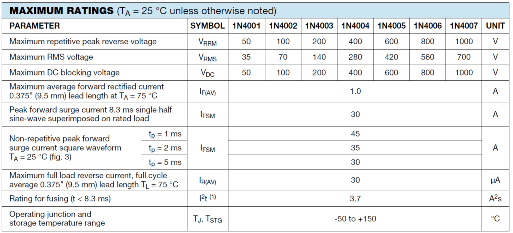
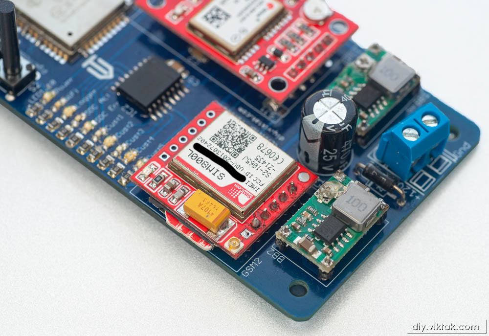
Obviously, the device will work from the 12V DC supply in the car (or 24V DC in a some buses/trucks). For polarity protection I added a 1N400x diode. According to its datasheet, it can provide 1A in continuous drive and can handle up to 30A for a few milliseconds. I only need a bit more than 2A at peak.
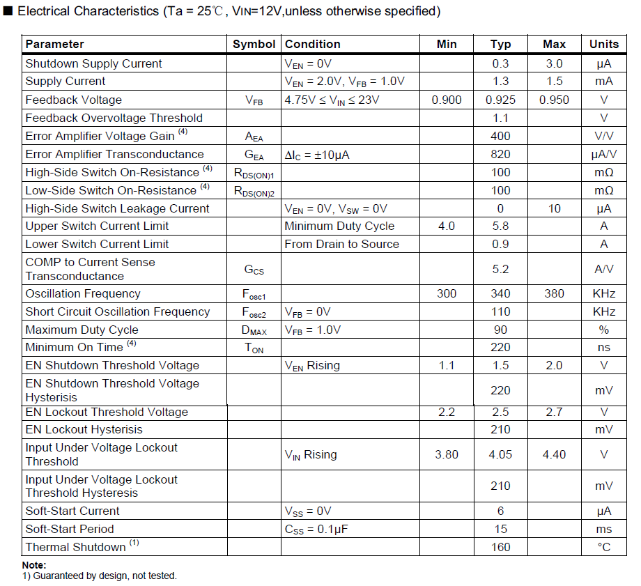
The GSM module requires a supply of 3.4V-4.4V. This range is pretty much out of the ordinary. The best way I found to produce this voltage is using a dedicated DC-DC converter (or Buck converter) that steps down the voltage from the car battery voltage to 4.2V. These cheap Buck converters have high efficiency (i.e. don’t heat up much as a linear voltage regulator) and come handy in similar projects. In fact, in this one I use two of them: one to power the GSM module, and one to provide 5V for the rest of the circuit.
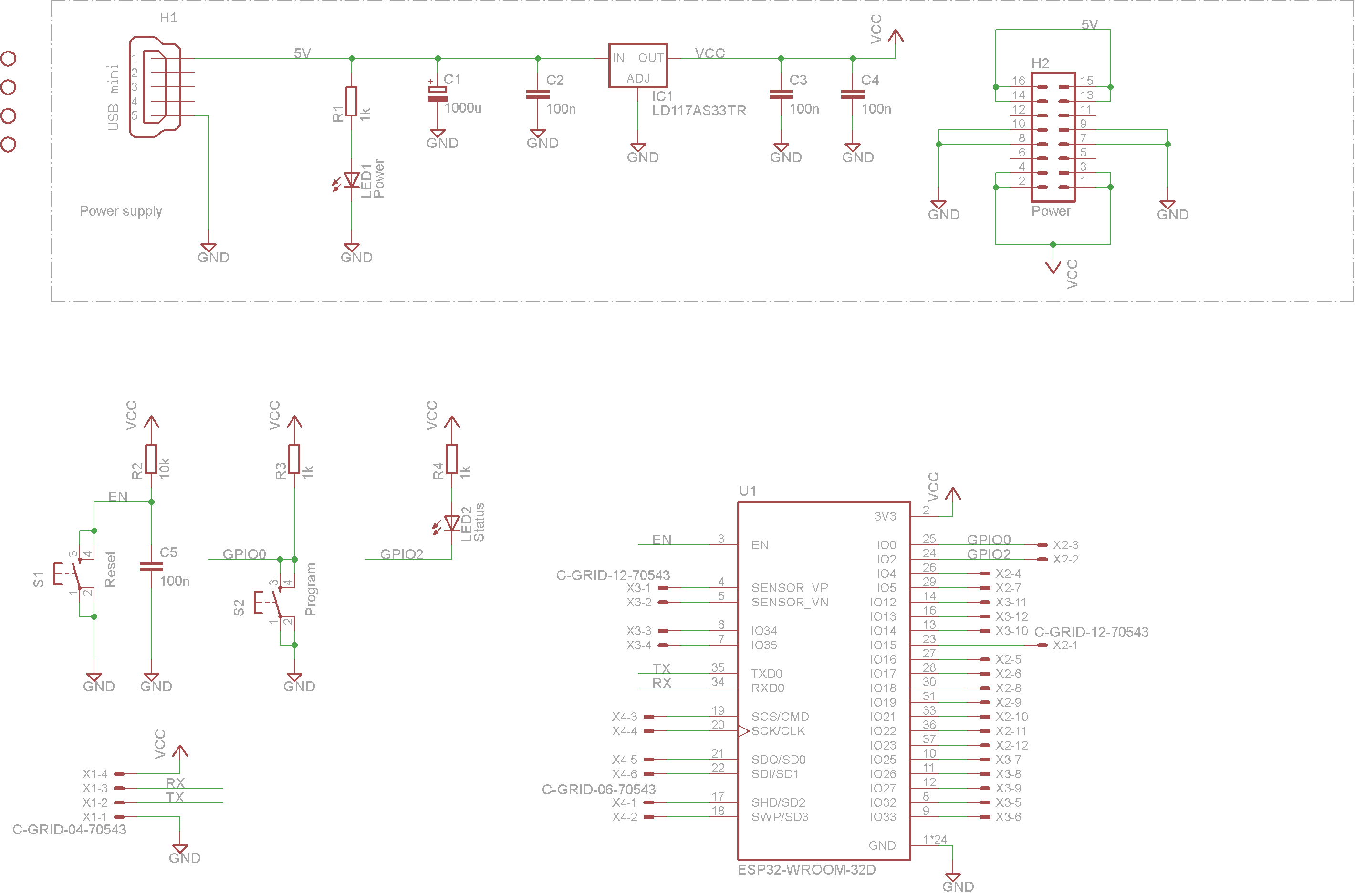
I also use an LDO to further step down the 5V to 3.3V for the ESP32, the SD card and the GPS. I could have skipped this and have the second Buck converter step down voltage directly to 3.3V, but I decided to have both 5V and 3.3V on the PCB so that in the future I can swap the GPS or the modem for a model that uses a different voltage. Then, all I have to do is adjust the output of that Buck converter.
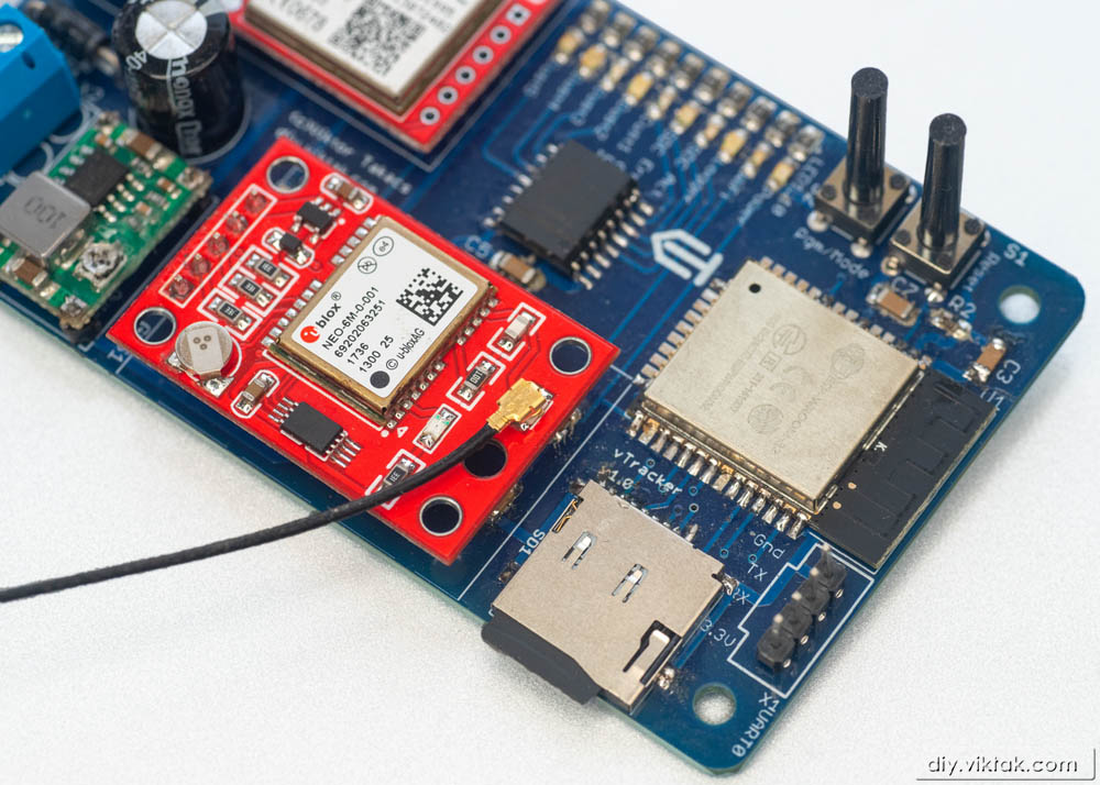
GPS module
The major driver in selecting the GPS module was its price and size. Since most, if not all, modern GPS modules work the same way, use the same algorithms to do their internal calculations, there is not really much difference between them. I am now talking about “ordinary” consumer grade GPS modules, that provide the location data via a serial line at 1 Hz or slower. I understand there are units that can provide you with the location data several times per second, but in a ground based vehicle that level of precision is not needed, so the extra cost is not justified.
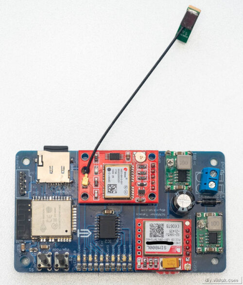
After looking at a few reasonably priced GPS modules online I also tried out a few different ones and finally decided to use a tiny module labeled NEO-6M GPS based on a NEO-M8N-0-10 chip in this project. The whole module is about 24mm*36mm and comes with a short ceramic antenna. It is so sensitive that even inside my house, although close to the window, it was able to get a fix easily. My PCB design allows the use of any similar GPS module through a header dedicated to a GPS module
According to its datasheet, it requires 3V to 5V to operate. In my circuit it happily operates from the same 3.3V as the ESP32, eliminating the need for a level shifter. It is important to provide the GPS with enough power, otherwise it will not get a fix, and instead of location data, it will output only something like this:
$GPTXT,01,01,02,HW  UBX-G60xx  00040007 FF7FFFFFp*53
$GPTXT,01,01,02,ROM CORE 7.03 (45969) Mar 17 2011 16:18:34*59
$GPTXT,01,01,02,ANTSUPERV=AC SD PDoS SR*20
$GPTXT,01,01,02,ANTSTATUS=DONTKNOW*33
$GPRMC,,V,,,,,,,,,,N*53
$GPVTG,,,,,,,,,N*30
$GPGGA,,,,,,0,00,99.99,,,,,,*48
When properly powered, the GPS spits out NMEA compatible GPS sentences once per second @ 9600baud, by default. This can be changed, but I left it untouched – it’s fine for my purposes. This is a sample output of a generic GPS module (I have changed the coordinates to random ones…):
$GPRMC,162724.00,A,3219.6528,N,02118.25426,E,0.085,,231020,,,A*70
$GPVTG,,T,,M,0.085,N,0.158,K,A*22
$GPGGA,162724.00,3219.6528,N,02118.25426,E,1,04,2.67,116.1,M,33.1,M,,*52
$GPGSA,A,3,05,13,09,15,,,,,,,,,3.71,2.67,2.58*01
$GPGSV,2,1,06,05,51,252,45,08,,,26,09,15,119,33,13,43,312,45*45
$GPGSV,2,2,06,15,10,307,45,17,,,23*48
$GPGLL,3219.6528,N,02118.25426,E,162724.00,A,A*66
Also, it has a 1Hz square wave output, which I have no use of, but could come handy in other projects.
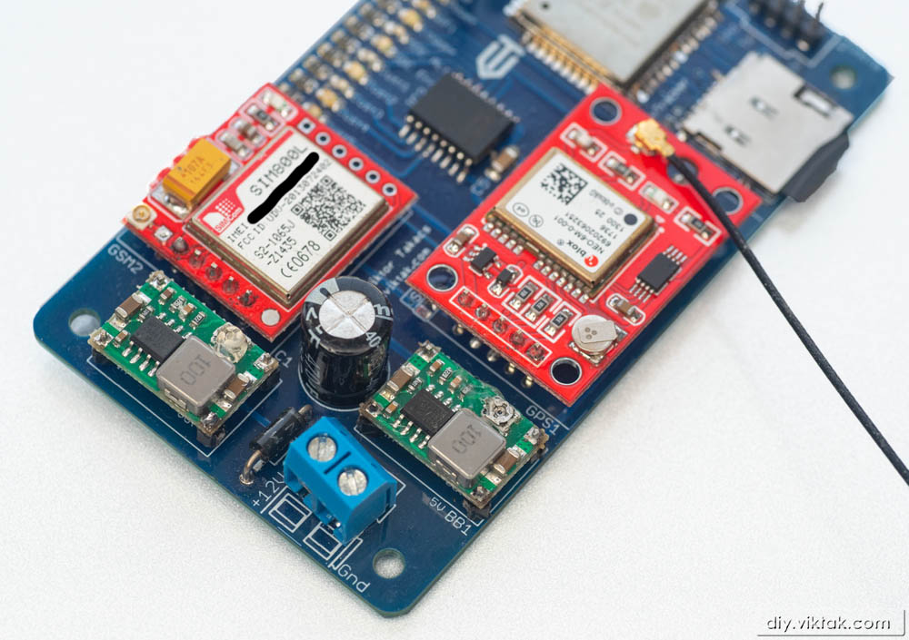
GSM module
For real time communication with the tracker I chose a tiny GSM module based on Simcom’s SIM800L. I picked this module because of its size, simplicity of use and price. For under €4 I get a fully featured GSM modem module with antenna. True, it works only on 2G networks, but in Europe (where I intend to use it) 2G networks are promised to run at least for a few more years because of the vast number of existing IoT devices.
Also, my PCB design allows for using any GSM module (3.3V or 5V) through a dedicated header as long as it can be also controlled by AT commands.
The modem can be programmed easily via a serial line using standard AT commands. During my experiments I found out, however, that this modem is very demanding in terms of power supply: According to its datasheet, during transmit busts it consumes 2A (!) peak, so its power supply should be able to handle that load. After a lot of experimentation I found that I could achieve reliable operation with a dedicated Buck converter that steps down voltage from the 12V available in the car to the optimal supply of the SIM800L, which is 4.2V. (I have tested the module with supply voltages covering the whole range specified in the datasheet (3.4V-4.4V))
Sample output of the SIM800L module using the TinyGSM+ library:
rst:0x1 (POWERON_RESET),boot:0x13 (SPI_FAST_FLASH_BOOT)
configsip: 0, SPIWP:0xee
clk_drv:0x00,q_drv:0x00,d_drv:0x00,cs0_drv:0x00,hd_drv:0x00,wp_drv:0x00
mode:DIO, clock div:2
load:0x3fff0018,len:4
load:0x3fff001c,len:1044
load:0x40078000,len:8896
load:0x40080400,len:5828
entry 0x400806ac
Wait...
Initializing modem...
[3666] ### TinyGSM Version: 0.10.7
[3666] ### TinyGSM Compiled Module:  TinyGsmClientSIM800
[3981] ### Modem: SIMCOM SIM800L
[3981] ### Modem: SIMCOM SIM800L
Modem Info: SIM800 R14.18
Waiting for network... success
Network connected
Connecting to internet success
GPRS connected
Performing HTTP GET request... Response status code: 200
Response Headers:
    Server : nginx/1.10.3 (Ubuntu)
    Date : Thu, 30 Jul 2020 08:39:49 GMT
    Content-Type : text/plain; charset=UTF-8
    Content-Length : 121
    Connection : close
    X-DNS-Prefetch-Control : off
    X-Frame-Options : SAMEORIGIN
    Strict-Transport-Security : max-age=15552000; includeSubDomains
    X-Download-Options : noopen
    X-Content-Type-Options : nosniff
    X-XSS-Protection : 1; mode=block
    Accept-Ranges : bytes
    Cache-Control : public, max-age=0
    Last-Modified : Wed, 27 Sep 2017 09:03:12 GMT
    ETag : W/"79-15ec2936080"
Content length is: 121
Response:

  _____            _____  _____  _____
    |  | |\ | \_/ |  ___ |_____ |  |  |
    |  | | \|  |  |_____| _____||  |  |


Body length is: 121
Server disconnected
GPRS disconnected
Output of HttpClient example of the same library:
rst:0x1 (POWERON_RESET),boot:0x13 (SPI_FAST_FLASH_BOOT)
configsip: 0, SPIWP:0xee
clk_drv:0x00,q_drv:0x00,d_drv:0x00,cs0_drv:0x00,hd_drv:0x00,wp_drv:0x00
mode:DIO, clock div:2
load:0x3fff0018,len:4
load:0x3fff001c,len:1044
load:0x40078000,len:8896
load:0x40080400,len:5828
entry 0x400806ac
Wait...
Initializing modem...[4219] ### TinyGSM Version: 0.10.7
[4219] ### TinyGSM Compiled Module:  TinyGsmClientSIM800
[4534] ### Modem: SIMCOM SIM800L
[4534] ### Modem: SIMCOM SIM800L
 [OK]
Modem Info: SIM800 R14.18
Unlocking PIN...
Waiting for network... [OK]
Connecting to internet [OK]
Local IP: 100.68.52.119
Connecting to vsh.pp.ua [OK]
.......
Server disconnected
GPRS disconnected

************************
 Received: 121 bytes
 Test:     PASSED
************************
CPU
When I started out on this project, I planned on using the good-old ESP8266 to be the brain of the operations. Unfortunately, quickly it turned out this project required some extra peripherals that the ESP8266 did not have. So I turned to the more recent ESP32, which has so much more power and has more peripherals than its predecessor, that most of them now is not even used. Anyway, it also presented me an opportunity to learn how to use a new micro controller.
First in the learning process I created a development board that made my life a lot easier. The USB development boards available on commercially are, in my mind, too dangerous to mess around with: one wrong move and, the best case, they can render your USB port dead, or the worst case, they can see your computer dead… I know from experience that I make mistakes occasionally, so ruining an expensive computer is not a question of “if” for me, but a question of “when”.
ESP32 development board. It contains:
- 3.3V power supply form an external 5V supply
- Reset/programming circuitry
- All GPIOs broken out to easily accessible pin headers
- LED indicators (one for power, one custom, connected to GPIO2)

For more of my development boards see my previous article.
Putting it all together
Here is the schematics of the final GPS logger:
As you can see, I also added an 8bit I2C IO expander and 8 LEDs to give some real time indication as to what is going on in the device when not attached to a debugger. In the prototype this will be useful, but in the production pieces I will simply not solder them on the PCB, since they are not needed during the day-to-day operation.
Naturally, I first put the whole circuit together on a breadboard, and only when I was satisfied that all components and features were working properly, I went on designing a custom PCB.

A word about the sponsor of this PCB: Although it would be possible to make this PCB at home, I opted for a professionally made one by PCBWay. I have used them in the past with success and I knew that the PCBs I order would turn out great. The ordering process was smooth, and within 24 hours of ordering, the finished PCBs were handed over to the post. The PCBs arrived in perfect condition, with plenty of protection around them. The soldering pads were all clean and soldering was a breeze, no cleaning of the PCBs first was necessary. I also found out to my surprise, that even though I ordered 10 PCBs, I got 11 in the box. Way to go, PCBWay! If you also want your own tracking device PCB professionally manufactured, click on the picture to the left and order your PCBs today!
Those parts that came in fully assembled modules were mounted on header pins, like daughter boards on a motherboard. This way I saved a lot of space on the actual PCB as I could place SMD parts under those big modules. Thus, the full size of the PCB was defined largely by these prefabricated modules.
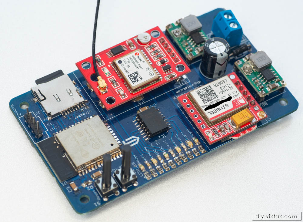
While I was designing the PCB several times I printed the design on a piece of paper and “fake” populated it with the major parts. I did this as I had no previous experience with the major parts of the design and wanted to make sure everything was in place.
All this to fit in a 100mm*60mm AB case found on eBay.
Firmware
I created a custom firmware for this tracker around the ESP32 chip. The firmware is fully open source and is available at my Github repository. I wrote the firmware using the Arduino framework for the ESP32 using the following additional open source libraries (in no particular order):
- ArduinoJson
- PubSubClient
- TimeLib
- Ticker
- Timezone
- PCF8574_ESP
- EspSoftwareSerial
- TinyGPSPlus
- TinyGSM
- StreamDebugger
- ArduinoHttpClient
All of them are excellent libraries without which development would have taken a lot longer. A huge thanks to all the open source creators!
My development environment is Visual Studio Code with PlatformIO on a 64 bit Windows 10 Professional system.
Operation
Before powering up the device a SIM card and an SD card need to be inserted. The SIM card is required for communication between the tracker and the server that collates the data sent from it. The SD card is needed to store location history locally, on the tracker. Both cards are optional, but at least one should be inserted, otherwise there is not much point using the device, although it will work.
Normal operation/Logging mode
Once powered up, after some initial self test, during a normal startup, the tracker will enter Logging mode, which means, that the GPS starts to get a location fix, and sets the system time from the GPS. In my experience, the GPS modules I tried get a fix within a minute, sometimes in a few seconds, depending on the time it has spent powered down. Once this is done, it starts logging location data to the SD card and to the server at user defined intervals. Also, at some other predefined interval, the tracker sends a “heartbeat” message to the server which contains basic diagnostics data about the device itself. The following is a typical example of such a message:
|
1 2 3 4 5 6 7 8 9 10 11 12 13 14 15 16 17 18 19 20 21 22 23 24 25 26 27 28 29 30 31 32 33 34 35 36 37 38 39 40 41 42 43 44 45 46 47 48 49 50 51 52 |
{ "System" : { "ChipID" : "ESP-XXX", "Node" : XXX, "Freeheap" : 272480, "HardwareID" : "ESP32-WROOM-32 BB", "HardwareVersion" : "1.0", "FirmwareID" : "GPS tracker", "FirmwareVersion" : "1.0", "UpTime" : "0:30:11", "CPU0_ResetReason" : "RTC Watch dog reset digital core and rtc module", "CPU1_ResetReason" : "for APP CPU, reset by PRO CPU", "FriendlyName" : "GPS Tracker/Logger", "TIMEZONE" : 2, "MQTT_SERVER" : "XXX.XXX.XXX", "MQTT_PORT" : 1883, "MQTT_TOPIC" : "tracker-XXX", "LOG_TO_SDC_INT" : 5, "LOG_2_MQTT_INT" : 30, "MAX_GSM_ATT" : 3, "HEARTBEAT_INTL" : 300 }, "SDCard" : { "CardType" : "SD", "TotalSpace" : 121765888, "UsedSpace" : 1949696, "AvailableSpace" : 119816192 }, "GPRS" : { "IMEI" : "XXX", "SIM_PIN" : "XXX", "GPRS_AP_NAME" : "internet", "GPRS_USER_NAME" : "", "GPRS_PASSWORD" : "", "IMSI" : "XXX", "LocalIP" : "100.XXX.XXX.212", "ModemInfo" : "SIM800 R14.18", "ModemName" : "SIMCOM SIM800L", "Operator" : "vodafone", "RegistrationStatus" : "REG_OK_HOME", "SignalQuality" : "18", "SimCCID" : "XXX" }, "WiFi" : { "APP_NAME" : "GPS Tracker/Logger", "SSID" : "Trabant", "PASSWORD" : "XXX", "ADMIN_PASSWORD" : "XXX", "AP_SSID" : "ESP-XXX", "AP_PASSWORD" : "XXX" } } |
The user has the option to remotely control certain aspects of the tracker using specially formulated MQTT messages. Here is a sample command message:
|
1 2 3 |
{ "command": "ListSDCardFiles" } |
The tracker will reply with something like this:
|
1 2 3 4 5 6 7 8 9 10 11 12 13 14 15 16 17 18 19 20 21 22 23 |
{ "type" : "FileList", "0" : { "name" : "20201002.TXT", "size" : 374470 }, "1" : { "name" : "20201003.TXT", "size" : 533589 }, "2" : { "name" : "20201001.TXT", "size" : 250408 }, "3" : { "name" : "20201004.TXT", "size" : 209334 }, "4" : { "name" : "20201005.TXT", "size" : 195464 } } |
The same way most of the settings of the tracker can also be changed remotely.
The location reports use the location format of Owntracks/NextTracks:
|
1 2 3 4 5 6 7 8 9 10 11 12 13 |
{ "_type" : "location", "acc" : 15, "alt" : 130, "batt" : 100, "conn" : "m", "lat" : xxx, "lon" : xxx, "tid" : "xxx", "tst" : 1602257435, "vac" : 2, "vel" : 0 } |
Using the Owntracks/NextTracks format allows me to use their free app on Android to view the vehicle(s) on the map. I prefer NextTracks as it doesn’t need to have Google Play Services in stalled on the phone.
Setup/Wifi mode
To enter Setup mode, just after powering up (but not before power is applied), the Program/Mode button must be held down for a few seconds. This signals the device during system boot to enter Setup mode. Also, if a normal boot fails a predefined number of times, the tracker will automatically enter Setup mode without user intervention.
Once in Setup mode, the tracker tries to establish a wireless connection with the last used WiFi network. If it cannot, it creates its own network. Either way, the user can now connect to it and set up the required parameters (like the MQTT server address, or logging interval) for normal operation. All user configurable settings are available through this built in web interface.
Backend
The server side of this solution takes care of receiving and storing any data received from the tracker. These are the back end components:
MQTT server
Strictly speaking, this is the only server side component that is critical. If we have this, then we can already see real time data coming from the tracker using, say NextTracks. It will not show us any historical data, but it has a nice user interface to show current location data for any number of vehicles.
In my setup I use Mosquitto as the MQTT server. I have written about installing it earlier.
Database
If we want to have historical data as well, we need to use a database to store the incoming location data. For this purpose I use InfluxDB, which I already have on my server for other projects.
Home Assistant
I also operate a Home Assistant instance on my server at home. It takes care of the usual home automation tasks, and as a bonus, its Owntracks integration implicitly uses InfluxDB to store all incoming data from the various sensors, my tracker’s location data is just one set of the many. So I literally had to do NOTHING to store location data.
Recently, I wrote about how to install and get started with Home Assistant, so I will not go into it here.
Grafana
Grafana is an excellent tool for displaying metrics, logs, etc in a beautiful and customizable web front-end. I have been using it for quite some time, and I just love the way my data looks every time I create something new. 🙂 It really is beautiful!
Trackmap Panel for Grafana is an open source plugin that allows displaying (historical) location data on a map.
Optional custom components
At the moment I don’t have any other custom component for this setup. This may change in the future if I find that Grafana’s or Nexttracks’ capabilities are not adequate. In this case I am likely to have to develop some custom components myself.
In my setup, at the time of writing this article, all the above back end components are performed by a single (very old) computer running Ubuntu Server.
Frontend
Mobile apps Owntracks/Nexttracks are ideal for getting a quick look at where the monitored vehicles are at a glance. If we want to get a more detailed view of how the monitored vehicles are doing any modern browser visiting the Grafana report will do the job. There one can see the path a given vehicle has taken in the past.
Security
By leaving this section to the end I certainly do not want to suggest that it is any less important. In fact, I think it is so important that I am going to dedicate a whole article just to that in the near future. Until then, happy tracking!

Nice! I want to make this.
Cool! Let me know when you are finished with it so that I can include it here! 🙂
Would be nice if you would sell the completed device on ebay or amazon. Is this 4g Sim compatible? The reason is 2G will be gone by 2022 (for t-mobile).
The current products on ebay/amazon/walmart are mostly 2G. The 4G compatible ones require a monthly fee that is quite high to keep track of bikes. Looks like if your product is solid a and can get past the deficiencies of existing Trakers, you have a market.
I am a software engineer but not a hardware expert 🙂
I decided by the 2G module because the 4G module is much more expensive. However, I can now see that many have asked for it, so I may create an updated version with a 4G module soon. In the meantime, you can simply swap a 4G module in place of the 2G module in the current design. It will probably not sit as nicely on the main board, but it is certainly feasible.
Nice. Would you consider selling units on ebay with the 4g module?
I don’t think I am going to sell this on eBay as this is not a professional, properly finished product. However, if you want one (or two 🙂 ) you can get it directly from me.
What are we looking at costwise for the 4g compatible unit? Interestingly, there is a seller in China now selling supposedly a 3g/4g compatible unit. Curious what components they are using and how they can sell it so cheap, inferior parts maybe?
https://www.ebay.com/itm/284244315979?epid=14027753467&hash=item422e480f4b:g:la0AAOSwA5Rdt2gQ
I’m not sure. Its reviews are not very good – especially around the 4G performance. Consider that the cheapest 4G module is over €30 on eBay as opposed to the 2G module which was around €3 (if my memory serves well).
For the parts alone, what are we looking at the totals? Also, is it something I can make make even though I do not have any electronic nor soldering skills? Sorry too many questions 🙂
Can you drop me a mail for prices? I don’t want to post prices here, because they change over time.
Good evening, I found your project on the hackday website and I must admit that it is very interesting.
In the description I can see that the project is open source, but I didn’t find any hardware related source files in the GitHub repository. Would it be possible to get the PCB layout source files or GERBER?
Please kindly reply.
Best regards,
Krzysztof
I’m afraid, I cannot give you the PCB files. From the schematics (in the article) you can easily recreate the PCB. Also, if you want to get an identical PCB, you can get one at https://www.pcbway.com/project/shareproject/GPS_tracker_recorder_for_cars_and_other_vehicles.html
Somehow I missed that it is possible to order on PCBWay 🙂 Thank you for the message
Hello, congratulations on a great project.
I’m getting a compilation error:
In file included from src/main.cpp:3:0:
include/includes.h:48:29: fatal error: TimeChangeRules.h: No such file or directory
What is the reason for this error ??
Greetings
You need to use this library: https://github.com/viktak/TimeChangeRules
I also updated the source with the new references – see main.cpp
Essentially, werever you see a missing namespace reference, just prepend the variable with “timechangerules::”
Sorry error again …
[{
“resource”: “/d:/TestProj/tracker/gps-tracker/.pio/libdeps/esp32dev/ArduinoJson/src/ArduinoJson/Document/JsonDocument.hpp”,
“owner”: “cpp”,
“severity”: 8,
“message”: “no matching function for call to ‘adaptString(char (*&)[6])'”,
“startLineNumber”: 250,
“startColumn”: 55,
“endLineNumber”: 250,
“endColumn”: 55
}]
Hmmm.. I don’t know about this one. As you can see, it comes from an external library I use (ArduinoJson), and it compiles just fine here. Try “cleaning” your project, restarting VS Code, things like that.
Hi,
How dit you solve the ESP reboot issue at GSM network connection ?
Thank you for you feedback
What “ESP reboot issue”?
Hi, sorry if I’m wrong
I believed that you did share a ESP reboot issue at GSM network connection in a forum.
It is a issue that I do encounter sometime with my board and I wanted to get your experience
Regards
Hmm, I cannot recall that… That is not to say it hasn’t happened 🙂 Do you have a link to that forum/post?
In general, my firmware regularly checks for GSM connection and if it is not available, it tries to reconnect a few times, then it HARDWARE resets the modem. I haven’t encountered a case where this was not enough.
Found it in my history : https://esp32.com/viewtopic.php?t=17776
On my side, the reboot depends on the GSM antenna model and position. I strongly suspect a noise on the Reset Pin, event if it is filtered. I’ve redesign a new PCB (4 layers instead of 2) . Hope that the power and ground layers will increase the stability.
Here is the product : https://www.instagram.com/p/ChPreGGNqUx/?utm_source=ig_web_copy_link
if you’re interested 😉
Ah yes, Now I remember! 🙂
So, that problem was indeed in insufficient power supply I used at the time. The modem draws a lot of power (up to 2A) for a short while when it is in use. The power supply I used at the time was not prepared for this. Also, adding a large capacitor (>470uF) solves this issue.
Since then I haven’t had a single issue.