
In the following I am going to describe my own version of the light panels that, in my view, eliminate all the disadvantages of the commercial products while keeping all the advantages. I am aware that others have made similar light panels. I am making and publishing my own version, because although I have seen many that had very nice features, but I haven’t seen one that combined all of the features important to me in one product.
As many others, I also like the concept of the Nanoleaf light panels. They have features that, in general, I appreciate and strive for in my own development efforts as well.
The major advantages are:
- Modular design – You can combine as few or as many (basic building blocks) as you want.
- Wireless remote control – You can select and fine tune the behavior of the light panels from your computer or phone.
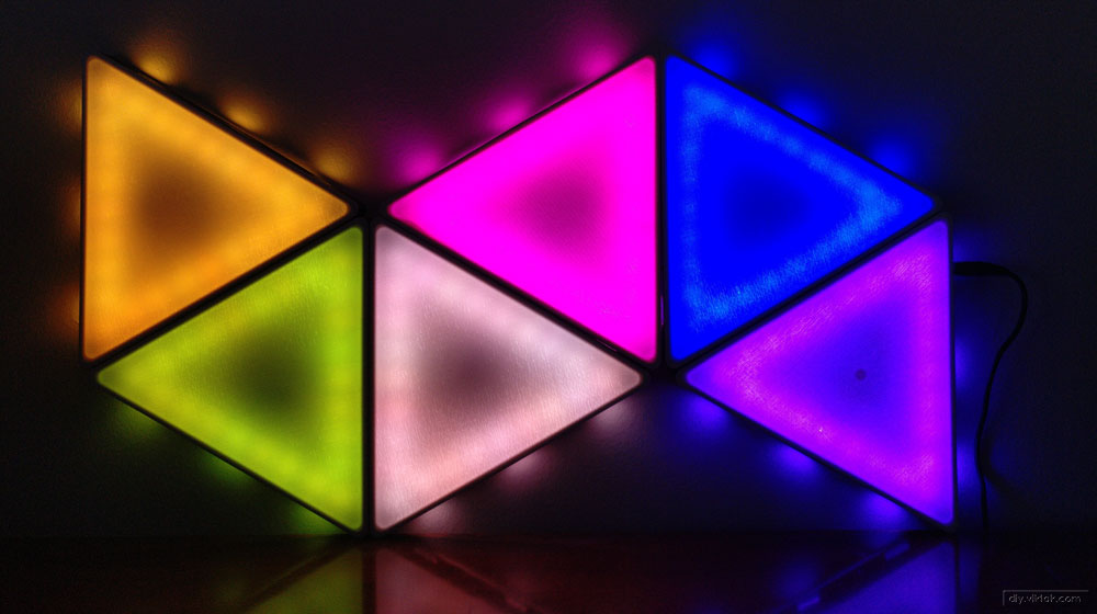
- Aesthetically pleasing – I am happy to put it in any room in my house.
However, there are a number of issues associated with them that prevent me from actually putting some of them there.
These include:
- Nanoleaf light panels are compatible with Apple HomeKit, Amazon Alexa, Google Assistant (and many more), which is simply a fancy way of saying: “in order to use our products, you have to give up your privacy”.
- Closed source – Apart from the privacy nightmare already mentioned, it also prevents one from examining the code for issues, or for learning purposes and making changes, adding/modifying features.
- Price – The cheapest kit you can get is (at the time of researching for this article) €189.99. This is waaay too expensive for the average people for a mood light.
Construction
Frame
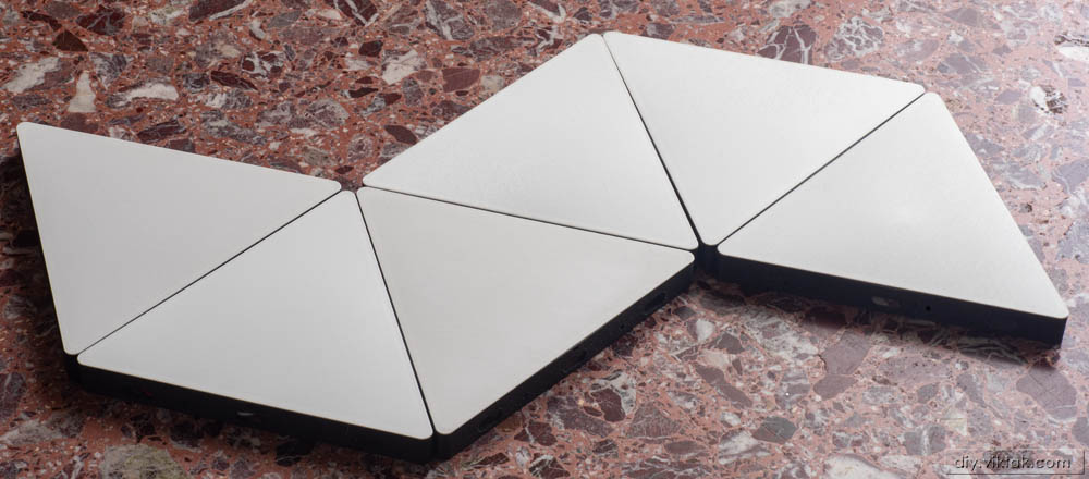
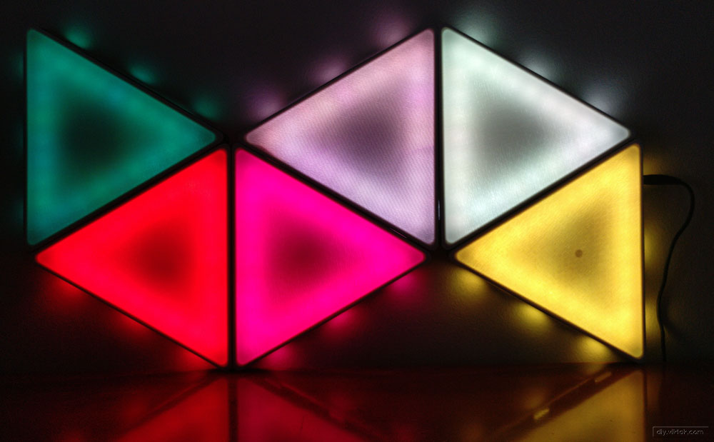
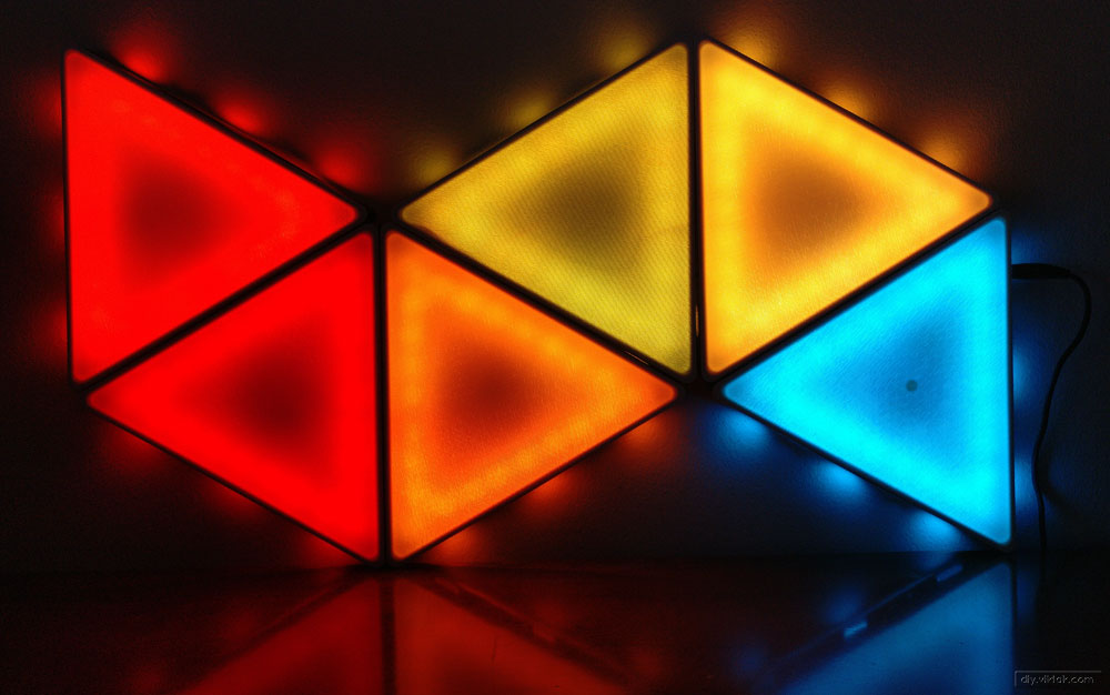
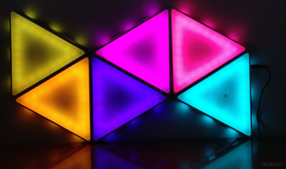
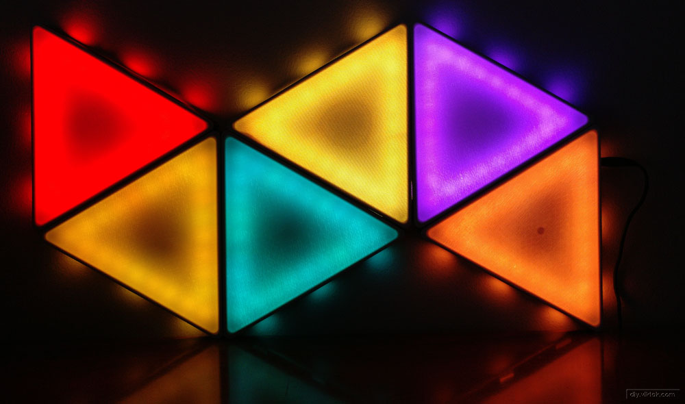
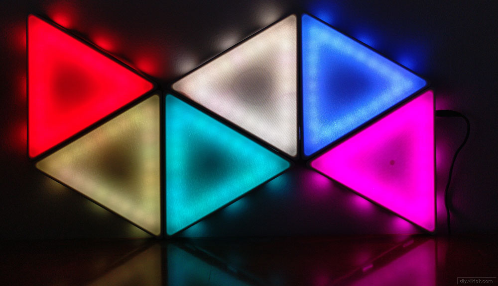
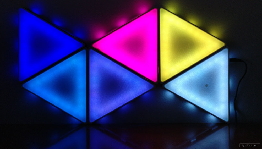
For the first iteration I decided to go with a triangle shape. The basic building of this design is an equilateral triangle. I chose this shape as this is the simplest shape you can get away for this project and at the same time it is challenging enough for me to learn 3D modelling. After reading up a lot on 3D modelling software and designing for 3D printing, I chose FreeCAD my weapon of choice as it is a free, cross platform and open source application with a great ecosystem and community around it. As it turns out, I am happy with my choice: With minimal help from online resources, I was able to design the frame for this project and more. For more advanced shapes, of course, I will need to learn more.
Each triangle unit consists of two 3D printed parts:
- Base: This holds the LED strips, cables and the controller circuit.
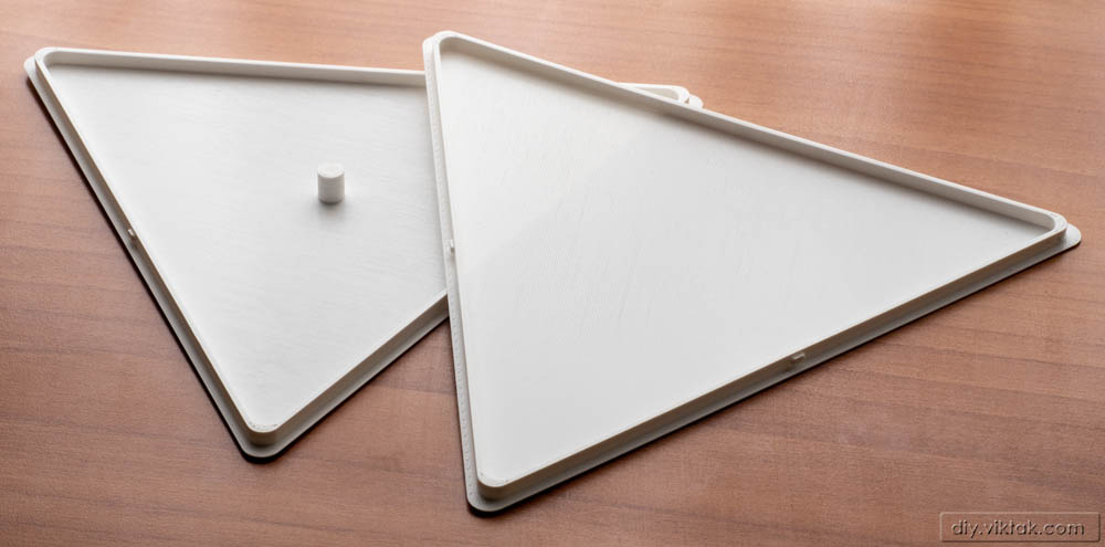
- Cover/Diffuser: A thin, white plastic sheet that is responsible for blurring the light so that the individual LEDs cannot be seen. After a couple of experiments, I found that a thickness of 0.6mm works really well. Technically, I made two different versions of this diffuser design: one for the triangle that has the controller in it, and one for all the rest of the triangles. The difference is that the one that goes into the triangle that has the controller has a little extension in the center of it to reach a button on the controller. It can be used to give some input to the controller, currently a short click there changes programs.
I printed the all the parts with PLA – black PLA for the base, white PLA for the diffusers. The printable files are available in the STL folder of the project’s repository.
The base and the diffuser panel have a hole and notch, respectively, to hold the diffuser in place. The triangle units are held together by screws on the sides of the base. On the sides there are also holes to allow for the cables passing from one triangle to the next. Finally, the base also have mounting holes that allow one to hang the final product on a wall.
Electronics
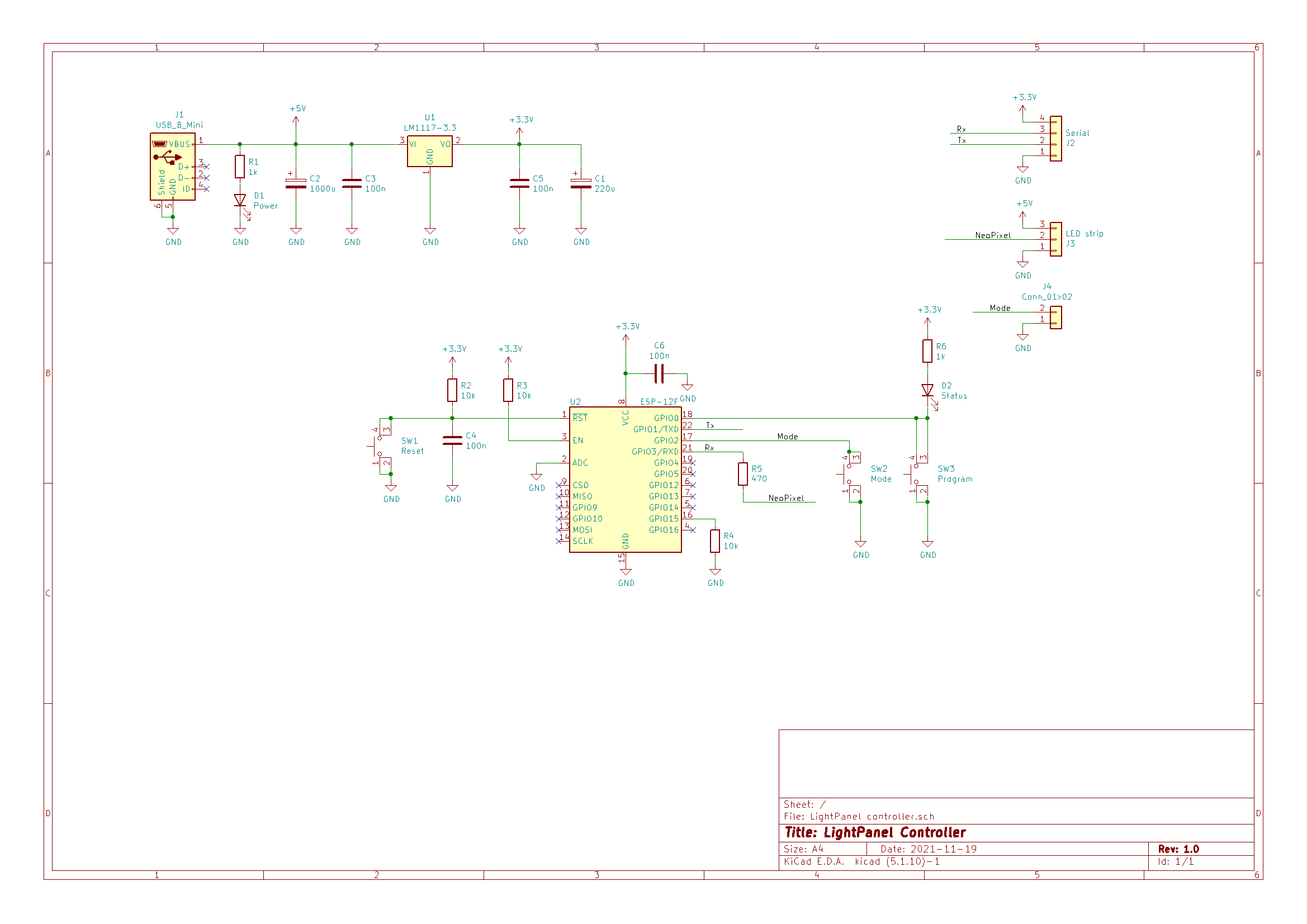
The controller circuit only contains very few parts. It operates from any power supply that provides 5V DC and as much current as required by the LEDs, which depends on the number of them used. My current setup has 6 triangle shaped units. Each triangle has 24 LEDs in them. According to measurements I made, the total current consumption is around 1.6A @5V. As most current smartphones/tablets use beefier power supplies, it is fair to say that this circuit can be powered by an ordinary phone charger. See later for more detailed explanation about the power requirements in general.
To illuminate the panels I chose to use pre-made strips of individually addressable RGB LEDs. These are called WS2812B LEDs, sometimes NeoPixel LEDs. I have used them in the past to make clocks and other gadgets.
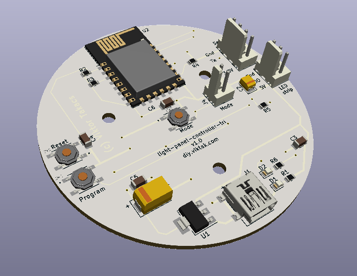
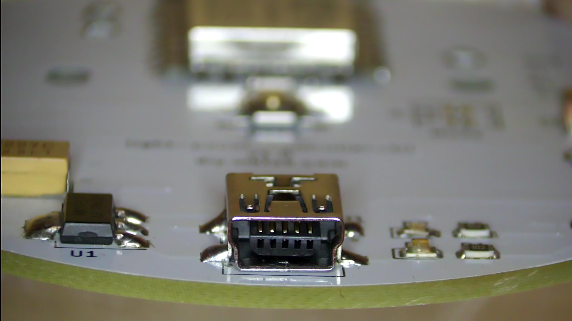
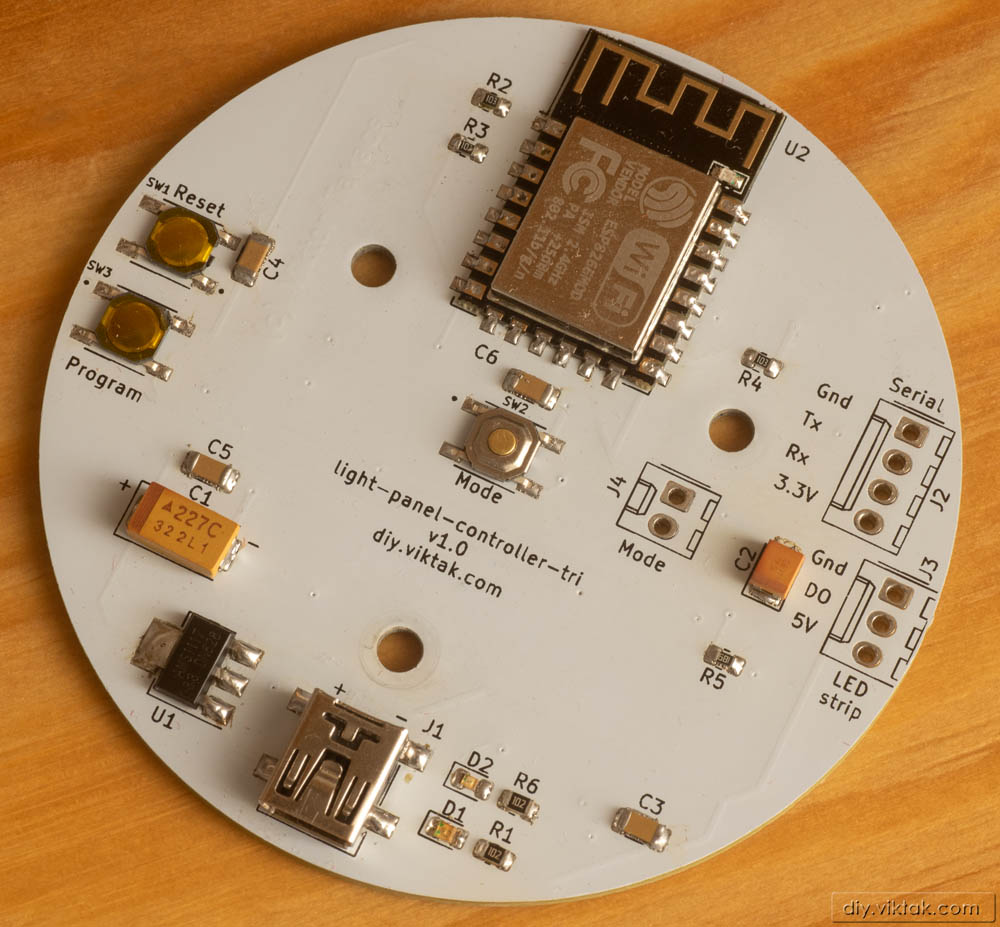
I designed a custom PCB for this project. Since I realized that I tend to use the same (or very similar) circuit in various projects, I designed a PCB that can be used in other projects as well. This meant to accept some compromises, e.g. the size of the PCB is quite big for this particular project, but ideal for another one (keep an eye for it on this blog!), or the fact that there is a USB mini socket for the power, although it will be impossible to plug the power there. Conversely, in another project there may be no need for the extra button (in the center).
A word about the sponsor of this PCB
Although it would be possible to make this PCB at home, I opted for a professionally made one by PCBWay. I have used them in the past with success and I knew that the PCBs I order would turn out great. The ordering process was smooth, and within 24 hours of ordering, the finished PCBs were handed over to the post. The PCBs arrived in perfect condition, with plenty of protection around them. The soldering pads were all clean and soldering was a breeze, no cleaning of the PCBs first was necessary. And get this: I ordered 10 PCBs, but, as usual, I got more in the box. This time I got 11. Awesome! If you also want your own custom PCB professionally manufactured, click on the picture to the left and order your PCBs today! Or click here to order your PCB for your own light panels!
One of the reasons I used PCBWay for this project is because they can do white PCBs, which is important in a lighting project: the PCB reflects as much light as possible. Strictly speaking, this is not necessary, but if it is easy to do (it is at PCBWay!), then there is no reason not to do it.
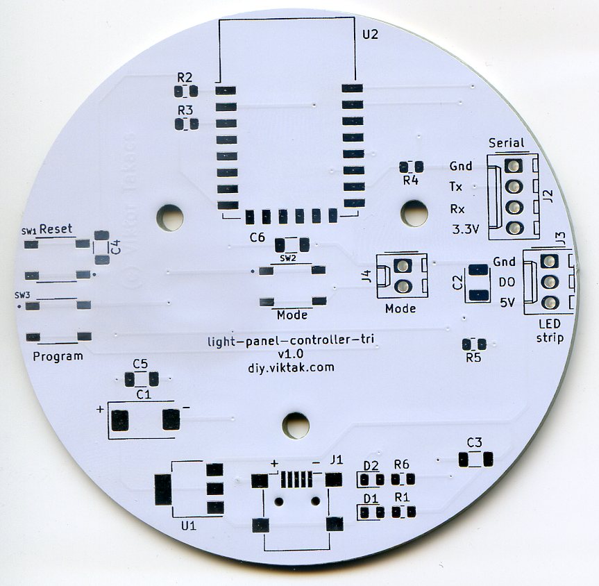
The PCB also has a programming header to facilitate the first programming of the ESP8266 micro-controller. It is best program and test the circuit before assembling the triangles.
Here is a full BOM for those wanting to build their own controller.
3D printed parts
The current design comprises of only three different 3D printable parts, the base and two different kinds of diffuser. Of course, you need to print as many copies as many triangles you want to have in your custom design.
Base triangle: The same design is used for all the triangles.
Diffuser for the first triangle: The first triangle is special, as it has the controller board, which has a push button in the center of it. This special diffuser design allows for the button to be pushed. However, if you don’t want to use the button (because you want to control it through its built-in web page), you don’t have to use this, but you can simply print one more of the other diffuser design.
Diffuser for all the subsequent triangles: This simpler design only differs from the previous one in the missing extension for activating the Mode button. The thickness of the diffuser is 0.6mm after a few test pieces. This seems to be a good value for diffusing the light so much so the individual LEDs cannot be seen.
All the above designs can be downloaded from the project’s repository.
Assembly
Assembling the final product is rather straightforward, although it involves several steps. Some of the steps required special attention as we will see:
1. Populate the PCB.
Not much to mention here apart from PCBWay: This time I also got a stencil which made applying solder paste a breeze.
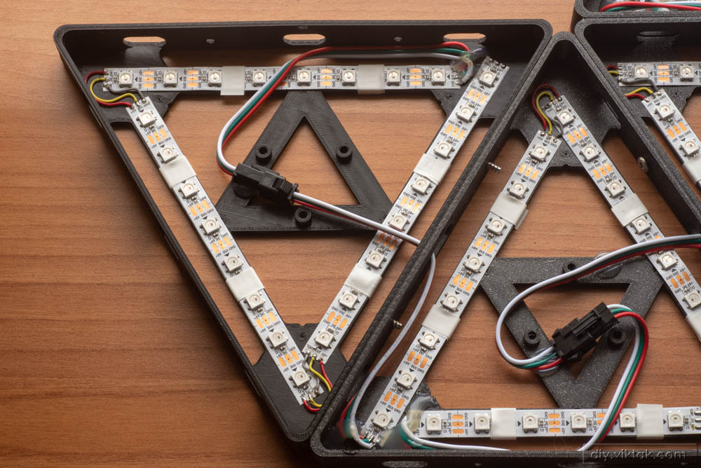
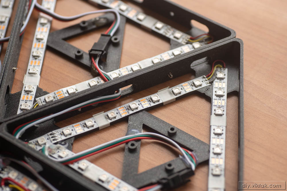
2. Cut 3 pieces of 8 LED long strips and mount them on the base triangle.
Although the LED strips I got have a sticky back for easy mounting, I found that as easily they can be mounted, they come off just as easily by the following morning… So after sticking them to the base, I also wrapped them around with electrical tape for peace of mind. It is a pity that they don’t stick well, because this adds a considerable time to making the triangle. I don’t know why they don’t stick, maybe they just don’t like PLA.
Also, care must be taken to mount the LED strips in a way that where one ends, the next one starts, i.e. the strips are directional.
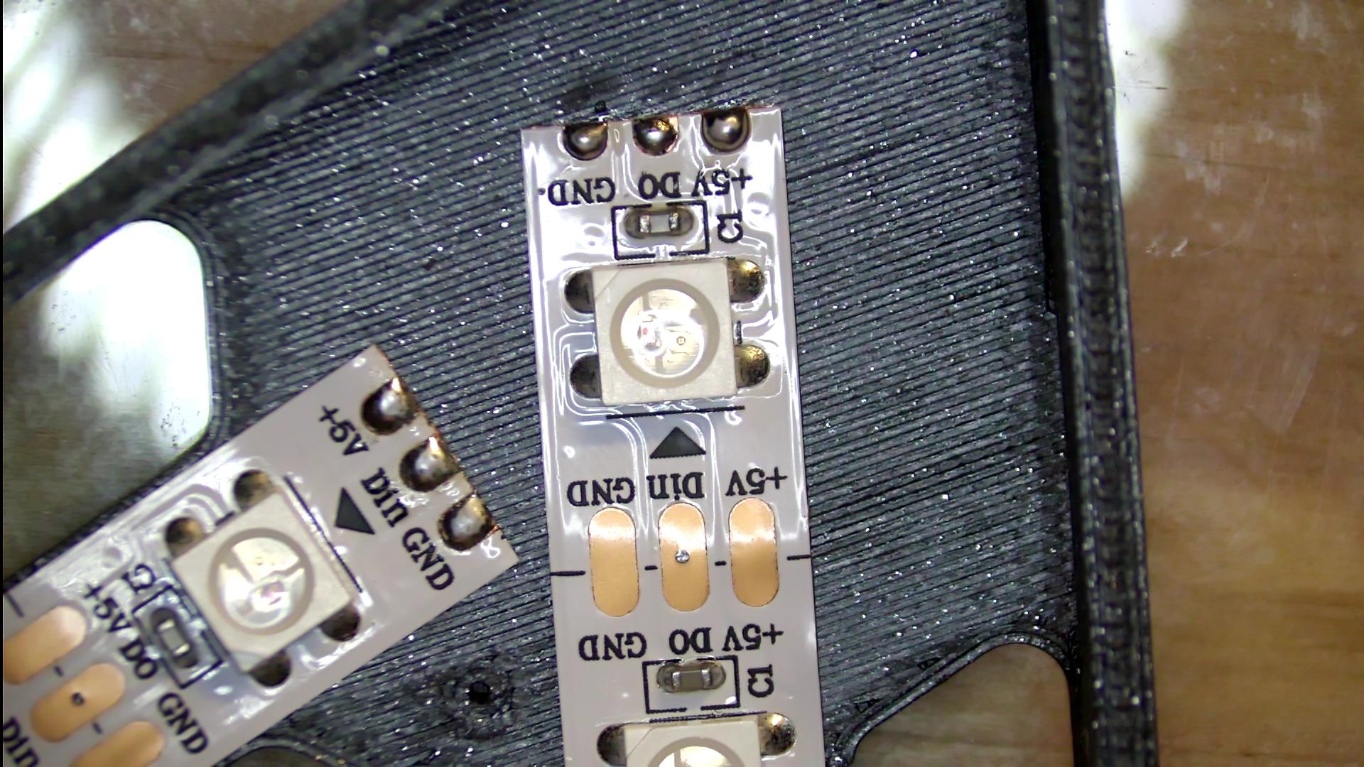
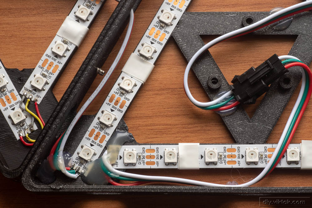
3. In two corners of the triangle solder small bits of wires between each strip.
The +, – and data lines must be connected by small wires. While the power lines are not directional, the data line is.
Also, the soldering has to be done very quickly, as the PLA base tends to melt after a second or two…
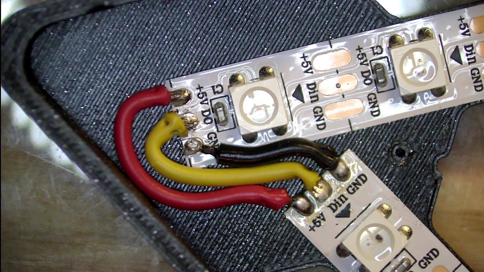
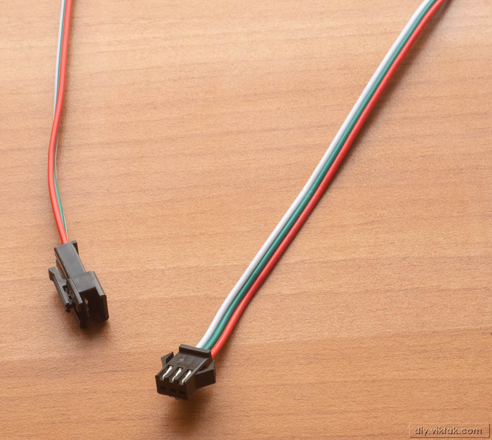
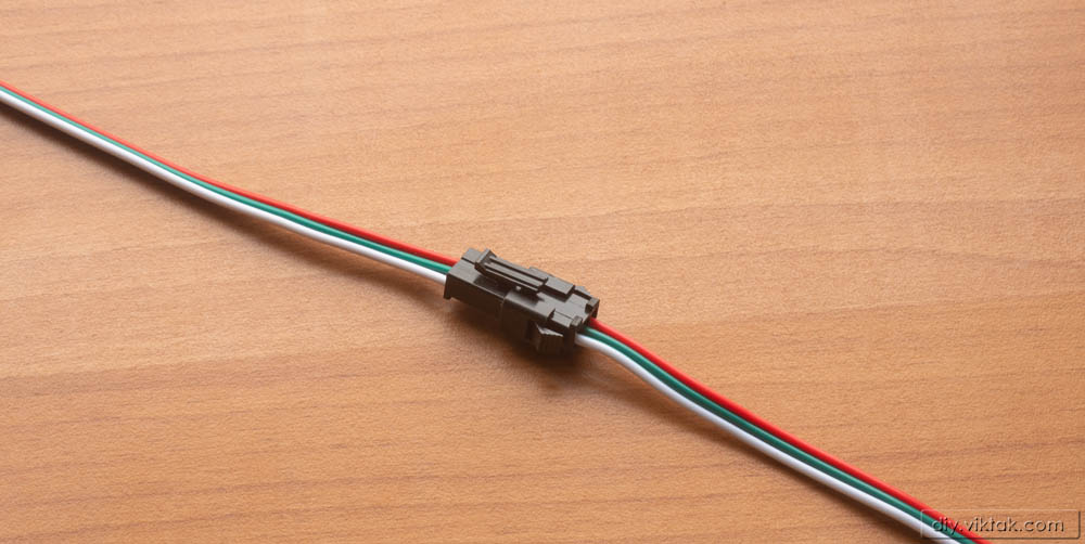
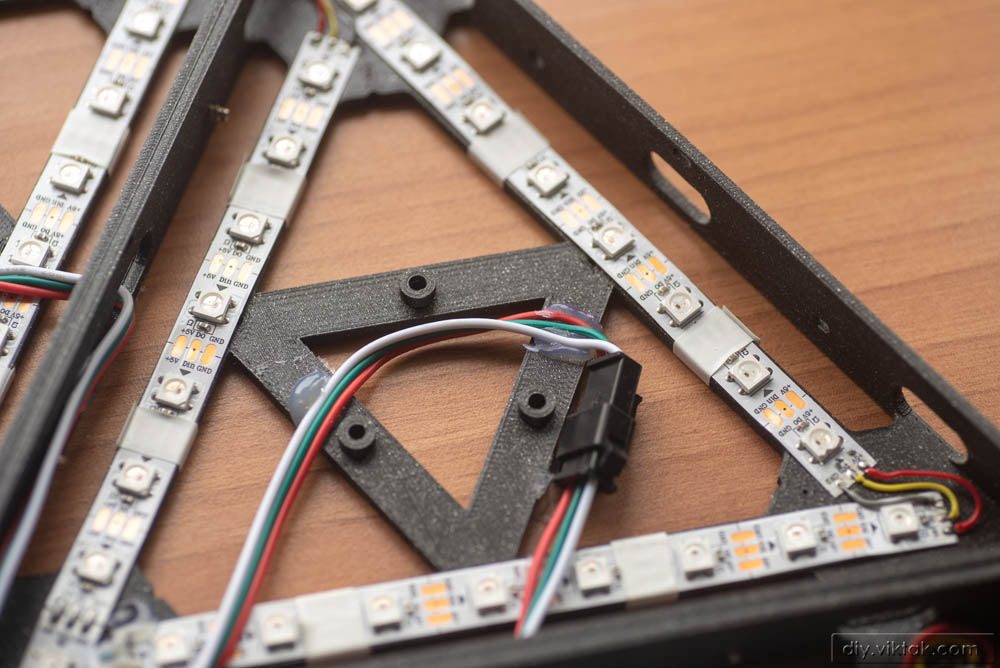
4. In the third corner solder special cables with connectors.
These connectors allow the triangles to be daisy-chained later for (almost) any design. I elected to use 3 pole SM connectors, because of their ease of use, readily availability and because they are polarized, i.e. you can’t connect two the wrong way. Solder the red wire to the +5V mark on the strip, the neutral colored (usually black or white) wire to the GND mark, finally the remaining wire to the data line.
Also, the base has holes on the side that allow one of the connectors to pass, but not the other. This way, the user is forced to rotate the triangles in the correct way when creating the final arrangement.
5. Repeat steps 2 to 4 as many times as many triangles you want in your final arrangement.
There is a theoretical limit as to how many triangles you can put together like this (the number of LEDs addressable in one continuous strip is over a thousand, which is a lot for a room), but it is not relevant for this application. An important consideration is, however, that the more LEDs we use, the more current it needs. At full power (all red, green and blue LEDs fully lit) each LED draws around 50mA current, which means a whopping 1.2A per triangle! Luckily, in this application, all the LED are never fully lit at the same time. As I mentioned earlier, in the light patterns I have, the maximum I measured was around 1.6A. For more current a bigger power supply as well as stronger cables are needed, maybe additional cables to carry the power to segments (triangles) further down the chain.
6. Mount a controller unit (PCB) in the center of the first triangle.
There are 3 mounting holes on the PCB aligning with the PCB support lugs on the base. Using 3 screws the PCB can be mounted securely in the center of the triangle. The USB mini connector will be positioned in a way that a power connector cannot reach it – that is OK, in this application of the PCB we don’t need it. In fact there is no need for it at all. I only populated it so that I could experiment with it easily before mounting it on the base.
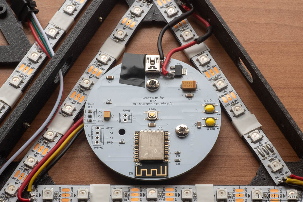
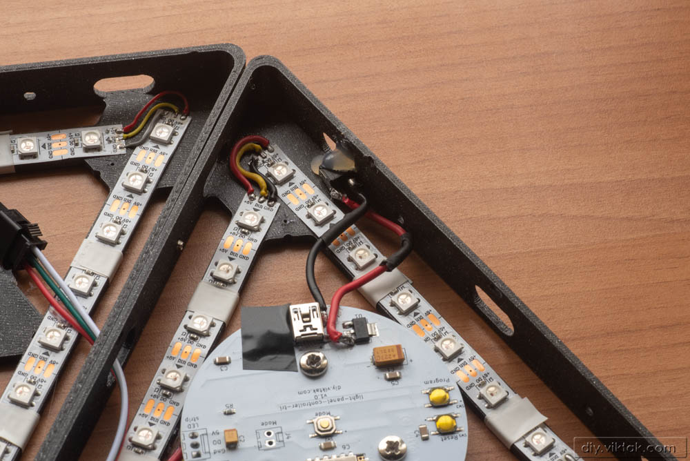
7. Hot/Super glue a power socket on the side of the first triangle.
I used a small barrel type connector. Also, I soldered the two small power cables between the connector and the PCB. On the PCB I don’t have dedicated soldering points for these cables, but there are plenty of big surfaces one can use.
8. Create the final layout.
On a big surface, i.e. the floor, I created my arrangement of the triangles. Here you can go crazy, the limit is your imagination! Just make sure each triangle is rotated in a way that its input/output corner makes sense. For example, if you want to continue the chain to the right, make sure the input/output corner is close to that, otherwise the connecting cables (remember, the ones with the SM connectors) will not reach each other.
9. Plug the input connector of each triangle into the output connector of the previous triangle.
Don’t worry about the polarity – if you soldered the wires correctly, they should be correct now.
It is a good idea to power up the whole thing to see if it works before moving onto the next step.
10. Make sure no cable/connector blocks the light coming from the LEDs.
Where the cable tension made a cable or a connector “stand up” too much from the back of the base, I used some hot glue and/or electrical tape to push them back safely to the back. This is an important step, because later a random cable or connector can cast ugly shadows on the diffuser panel. the easiest way to find out if no shadows will be cast, if you temporarily put the diffuser panel on the base.
11. Secure the triangles to each other.
Using two small screws per triangle-side, finalize the triangles. I used some leftover screws from PC cases.
12. Cover all the triangles with a white diffuser.
Make sure, the triangle with the controller gets its special diffuser, with the button extension in the center.
Now the arrangement is ready to go on the wall!
Firmware
To write the firmware I used Visual Studio Code with PlatformIO.
The firmware for this project is very similar to my previous ESP8266 based projects. I used the same framework, only changed/added parts that are specific to this application. As such, the operation of the light panels can be customized on the built in web pages.
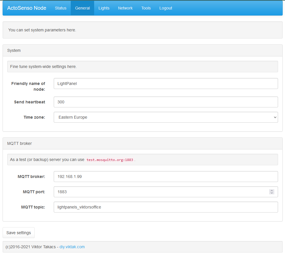
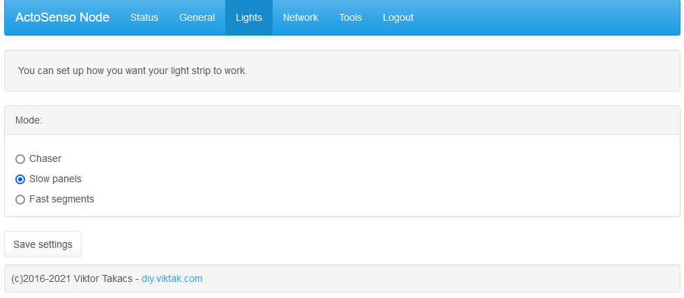
Clicking the center of the first triangle (remember the button extension?) changes the light pattern. The firmware also takes commands via MQTT, so if used in conjunction with a separate automation system (i.e. Home Assistant), it can also display different light patterns based on some real life sensors, events. At the moment there are only three different programs, but I plan on expanding them greatly in the near future.
The source code is available in GitHub.
Summary
The finished product (which is, of course, never finished!) has the following features:
- Fully open source – you can make your own, or you can change the way it works.
- Modular design – you can put as many or as few into your arrangement, as you like.
- Fully 3D printable – using the most user friendly, easily printable PLA, you can make your own light panels.
- Can be controlled wirelessly – you can change its behavior from your mobile phone using your home’s WiFi, if you wish.
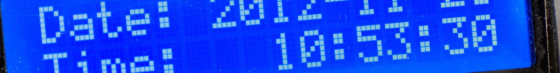
- Can easily be integrated into a home automation system – you are not limited to abstract (meaningless) patterns/shapes on the display, but you can configure it as a human interface: i.e. if someone rings the doorbell, or you get mail, the pattern shown changes to visually alert you. It can even tell you the time! Or use it as an alarm clock! The possibilities are endless!
- Affordable entry – You don’t need to rob a bank to get started. The cost of materials is a small fraction of the commercially available products. You can also expand your arrangement with as little as one additional triangle.

Hi!
Excellent project! It is great to see an DIY alternative to the massively overpriced originals finnaly out there.
One question though, why chave you decide to use tantalum capacitors for C1 and C2?
thanks for stopping by!!! 🙂
Simply because of size. I wanted the (assembled) PCB to have the smallest profile possible as I am using it in other projects as well where there is even less space above it.
The github repo doesn’t seem to be available. Is that intentional?
Of course not! I simply forgot to set it to public when I published the article. It is available now.
Thanks for reminding me!
Thank you 😉
Hi – thanks a lot for the article, It is inspiring and a very nice project !
#1
From my perspective the article could be improved upon with a more visible part-list, I have trouble to find a clear BoM to evaluate cost and effort, which would be my main considerations to decide If I would try to build my own version.
#2
Do you possibly plan to sell small batches of pre-soldered controller boards on a portal like tindie.com or similar?
Thanks for your kind words.
#1
I just uploaded one here: https://github.com/viktak/Light-Panels/tree/main/bom I will also put it in the article.
#2
Yes, I am planning to sell some kits, and I will eventually have a dedicated page for it somewhere on this blog, but I cannot say a definite time when it will happen.
Hi I was just curious would a type C header work on the pcb board?
If you mean in general, then of course, a USB-C connector could do the same job. However, if you ask about the current design, then the answer is no, the USB-C connector has a different footprint than the mini USB I have in the actual design.
Can you provide me with the PCB source file I can’t buy it here at PCBWAY and it won’t arrive by courier Thanks
I’m afraid I can’t t do it. It is easy to recreate using the schematics above.
Where are you located? Maybe I can send you a PCB?
One Question,
what is ur power connector if u dont use the usb port?
And in my world u need 1,2A x 6 triangles = 7,2A !!!
So… u need 5v 10A power supply, right ?
As you can see in the pictures above, I use a barrel connector on the side of the first triangle. That connector can take a few amperes. From the barrel connector some thick wires go to the PCB where they are soldered directly on some larger surfaces (like the pins of the LDO – see the pics) directly.
Yes, your calculations are correct, I also did them with the same results, as pointed out in the article. However, that is only a maximum value, only applicable if all the LEDs are cranked up to max brightness (all colors) at the same time and for a longer time. As I mentioned, the actual current consumption is around 1.6A with the patterns I use, the patterns that are currently in GitHub. I have been operating these panels in my office for the last few months 24/7 on an old 2A phone charger.
Of course, if you plan on using it with more brightness, you need a stronger power supply, as you mentioned a 5V 10A one would be perfect.
How can i configurate the ESP?
Im new in this buisness. My first attention was to open something like a .exe in your github, but there is only a config typ.
Can you help me a little bit?
Thank You for the first time.
Sacha,
You have to upload a binary file to the ESP8266. There are several tutorials on the internet showing you how to do it, so I’m not going to.
The github repo only contains the source files for my projects. This ensures there is no funny business going on in the binary file (that you wouldn’t be able to verify what it contains).
I would suggest you start at the beginning, for example, by downloading VS Code/PlatformIO, which is an excellent IDE for developing for the ESP:
https://platformio.org
Once you have it installed on your computer, create a copy of all of the files in my repo, open it in PlatformIO. PlatformIO also gives you the option to upload firmware to the ESP using a serial port or wifi.
This is the generic idea, if you run into a specific problem, let me know, I’ll try to help.
Error:
11 | #include “TimeChangeRules.h”
| ^~~~~~~~~~~~~~~~~~~
compilation terminated.
*** [.pio\build\esp12e\src\network.cpp.o] Error 1
.pio\libdeps\esp12e\PubSubClient\src\PubSubClient.cpp: In member function ‘boolean PubSubClient::publish_P(const char*, const uint8_t*, unsigned int, boolean)’:
.pio\libdeps\esp12e\PubSubClient\src\PubSubClient.cpp:523:16: warning: comparison of integer expressions of different signedness: ‘unsigned int’ and ‘int’ [-Wsign-compare]
523 | return (rc == expectedLength);
| ~~~^~~~~~~~~~~~~~~~~
src\main.cpp: In function ‘void setup()’:
src\main.cpp:20:43: error: ‘FIRMWARE_VERSION’ was not declared in this scope
20 | String FirmwareVersionString = String(FIRMWARE_VERSION) + ” @ ” + String(TIME) + ” – ” + String(DATE);
| ^~~~~~~~~~~~~~~~
*** [.pio\build\esp12e\src\main.cpp.o] Error 1
src\mqtt.cpp: In function ‘void mqtt::SendHeartbeat()’:
src\mqtt.cpp:71:41: error: ‘FIRMWARE_VERSION’ was not declared in this scope
71 | sysDetails[“FirmwareVersion”] = FIRMWARE_VERSION;
| ^~~~~~~~~~~~~~~~
*** [.pio\build\esp12e\src\mqtt.cpp.o] Error 1
Something with TimeChangeRules and “Firmware_Version”
This happend via compilation.
TimeChangeRules:
https://github.com/viktak/TimeChangeRules
Version: I use a script to generate a version number at each build. Its result is something like this (create a new file – version.h – with this content and you’ll be good to go):
///////////////////////////////////////////////////////////////
//
// WARNING: This file is generated automatically,
// all changes will be lost.
//
///////////////////////////////////////////////////////////////
#ifndef BUILD_NUMBER
#define BUILD_NUMBER “837”
#endif
#ifndef FIRMWARE_VERSION
#define FIRMWARE_VERSION “v1.1.837 – 2022-03-25 18:10:29.322883”
#endif
#ifndef FIRMWARE_VERSION_SHORT
#define FIRMWARE_VERSION_SHORT “v1.1.837”
#endif
Timechangerules works, ty 😀
Version is broken:
In file included from src\main.cpp:1:
include/version.h:9:22: error: extended character “ is not valid in an identifier
9 | #define BUILD_NUMBER “837”
| ^
include/version.h:9:22: error: extended character ” is not valid in an identifier
include/version.h:12:26: error: extended character “ is not valid in an identifier
12 | #define FIRMWARE_VERSION “v1.1.837 – 2022-03-25 18:10:29.322883”
| ^
include/version.h:12:38: error: extended character – is not valid in an identifier
12 | #define FIRMWARE_VERSION “v1.1.837 – 2022-03-25 18:10:29.322883”
| ^
include/version.h:12:59: error: extended character ” is not valid in an identifier
12 | #define FIRMWARE_VERSION “v1.1.837 – 2022-03-25 18:10:29.322883”
| ^
include/version.h:15:32: error: extended character “ is not valid in an identifier
15 | #define FIRMWARE_VERSION_SHORT “v1.1.837”
| ^
include/version.h:15:37: error: extended character ” is not valid in an identifier
15 | #define FIRMWARE_VERSION_SHORT “v1.1.837”
Even without ” the “v1.1.837 – 2022-03-25 18:10:29.322883” is wrong.
I think the problem is that you copied and pasted it from wordpress directly and those quotation marks are all messed up. Try replacing those with “normal” double quotes or single quotes and it will work.
Oh yeah, it was 😀 .
Uploaded, try to connect to the acces point and… nothing.
After connecting i try to connect to “192.168.4.1” into my browser:
192.168.4.1/login.html
This will appear with an empty site 🙁
Seems to me that you only uploaded the code, not the file system (for the web pages).
In PlatformIO you also need to upload the file system under PlatformIO->esp12e->Platform->Upload Filesystem Image
Once that is done, you will see the actual web pages. To login, use admin/admin.
Ty Viktor 😀
It works by now.
Which language should i learn for the next step !?
C or C++ ? I want to learn to do projects like u by my self.
Do u have any advice for me ? And in which language is your project writen?
PS: If i have finshed my project, i can show my resulkt 😀
Well done!!! :):):):)
This project was written in c++.
I don’t know what to recommend to you as a language to learn because there are many. It depends on your history (as in what programming languages you already know) and your preferences.
Most languages (that apply to the ESPs) have a large community (to help you when you hit a wall) and have a large variety of available open source libraries that can speed up your work.
Specifically on the ESPs, a quick search showed this top options:
https://www.electronicdiys.com/2018/11/programming-languages-for-esp32-esp8266.html
However, this is far from a complete or even a usable list. 🙂
I’m sorry I can only give you generic answers to generic questions.
I want to learn a language for scripting my self projects like your, mainly ESP/Arduinos.
I dont want to be bottlenecked by a language.
Maybe easy
“fast to learn”
lots of options (smart home, controlling led and maybe networking)
I dont have knowledge with any language by now, so its hard to take a decision for me.
Well, then starting with c++ in the Arduino framework (like this project) is a good choice, I think.