
Introduction
Over the years I have collected quite a few laptops (among many other things…). I usually pick them up when my friends and relatives get a new laptop and they throw away the old ones. Most of these laptops are not working and/or very old (i.e. around 15 years old, sometimes even more). I collect them because, even though they are not usable any more as laptops, I can sometimes fix them up just so much that they can be converted to a digital picture frame, or I remove some parts of it and make use of those in some way, like use a laptop touchpad on a PC.
Since I was running out of space to store these laptops, a few weeks ago I decided to remove the usable parts from some of the very old laptops that were beyond hope, and recycle what’s left of them.
The shiniest part you can salvage from an old/broken laptop is arguably the LCD panel. Most of the time the LCD panel of an old laptop has no problem at all (if there is a problem with the display of a laptop it’s mostly not the LCD panel itself but the inverter).
 |
| An old LCD panel used as a monitor for a Raspberry Pi |
Below I am demonstrating a way of giving these (in my opinion) fantastic pieces of engineering pieces a new life.
Research
To make an LCD panel work you need two main items, both specific to the LCD panel:
- an LCD driver circuit with an appropriate connector for the LCD panel
- an inverter circuit
After a short research on the subject on the internet it became clear that, although theoretically it seems like an easy job to find matching pieces, there are many variations of the above circuits and it’s easy to get the wrong ones. To make matters worse, you usually have one shot: you either get the right components for the first try, or the LCD panel gives you negative feedback in the form of smoke signals…
Most on-line retailers have no idea what driver and inverter a particular LCD panel requires. They expect you to know what exactly you are looking for. (Which is probably right, from a technical point of view, but they lose a lot of business by not being able to help non-LCD-specialist customers.) Since I know next to nothing about LCD panels I was looking for a retailer who could provide me with a kit specific to my LCD panel based on the model number of my LCD panel (which is always clearly printed on the back of the LCD panel).
After searching and searching I finally found an eBay seller (e-qstore) who seemed to be able to help me with any question I threw at her. Not only that, but I got replies to most of my questions within minutes!
After just a few e-mails I was ready to order not one but two kits for two of my LCD panels to give them a try. I have many more LCDs to salvage this way and if this method works out I will order more kits from the same seller, for sure, won’t bother experimenting with other sellers.
A couple of weeks later the kits arrived and I immediately tried them out.
Identifying the parts in the kit
Each LCD panel requires a specific set of driver and inverter modules. These modules look a bit differently for each, however, once you have the right kit for your LCD panel in your hands, figuring them out is pretty straightforward.
In a kit, usually, there are 3 PCBs with several bunches of cables sticking out of them left, right and centre, like this:
 |
| Just out of the box – all the parts of the kit come connected to each other. At least we don’t have to figure the connection in between them. |
The parts in detail, left from right:
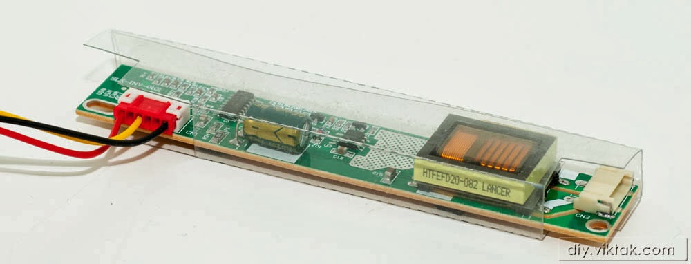 |
| Inverter: this produces the high voltage needed for the LCD backlight. You are not supposed to touch it while in use. It comes in protective plastic, so it’s really difficult to get electrocuted… |
 |
| Driver board: This sits in between the LCD panel and the source of the video, typically a computer of some sort. |
 |
| Monitor control panel board: this is used to control the display settings, i.e. brightness, contrast, etc. My model has an OSD menu. This is connected to the driver board already, nothing else to set up or connect. |
Assembly
The pictures following come mixed from the two LCD panels I got – the steps for both (and probably most LCD panels) are identical though, and only the used kits are different.
The assembly starts with stripping the LCD panels from all previous covers, connectors, cables, etc.
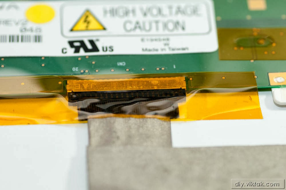 |
| The old ribbon cable that connected the LCD panel with the laptop. |
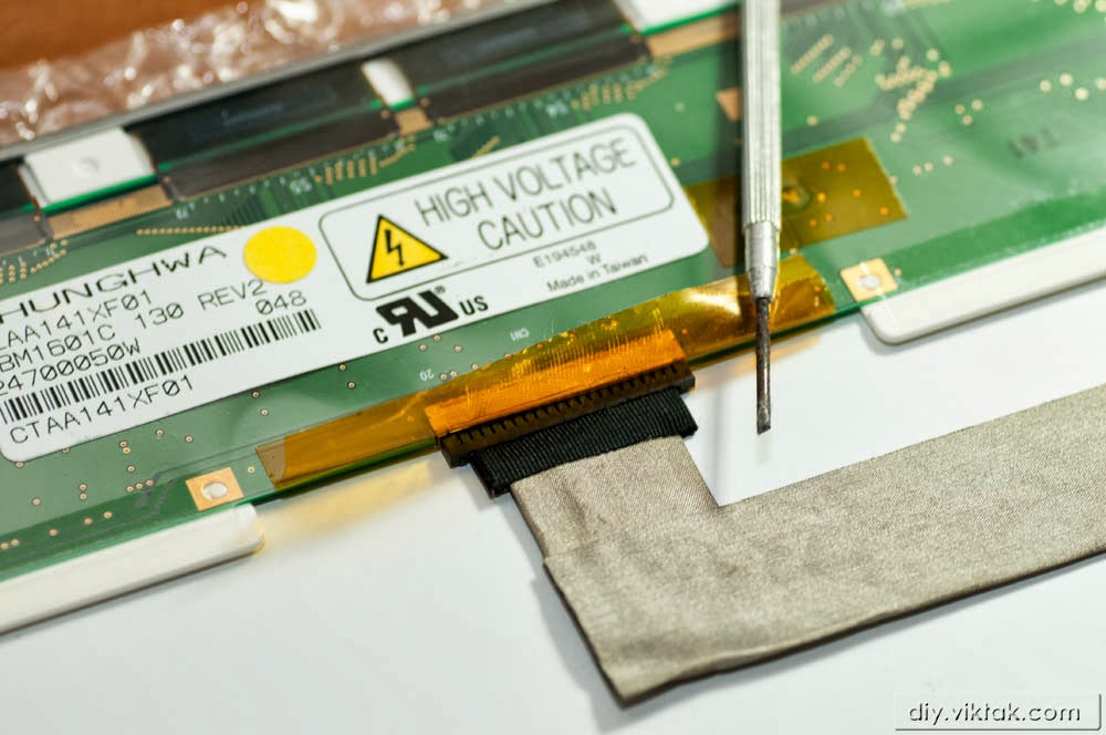 |
| Gently lift the sticky tape that holds the ribbon cable in place, then remove the ribbon cable altogether. |
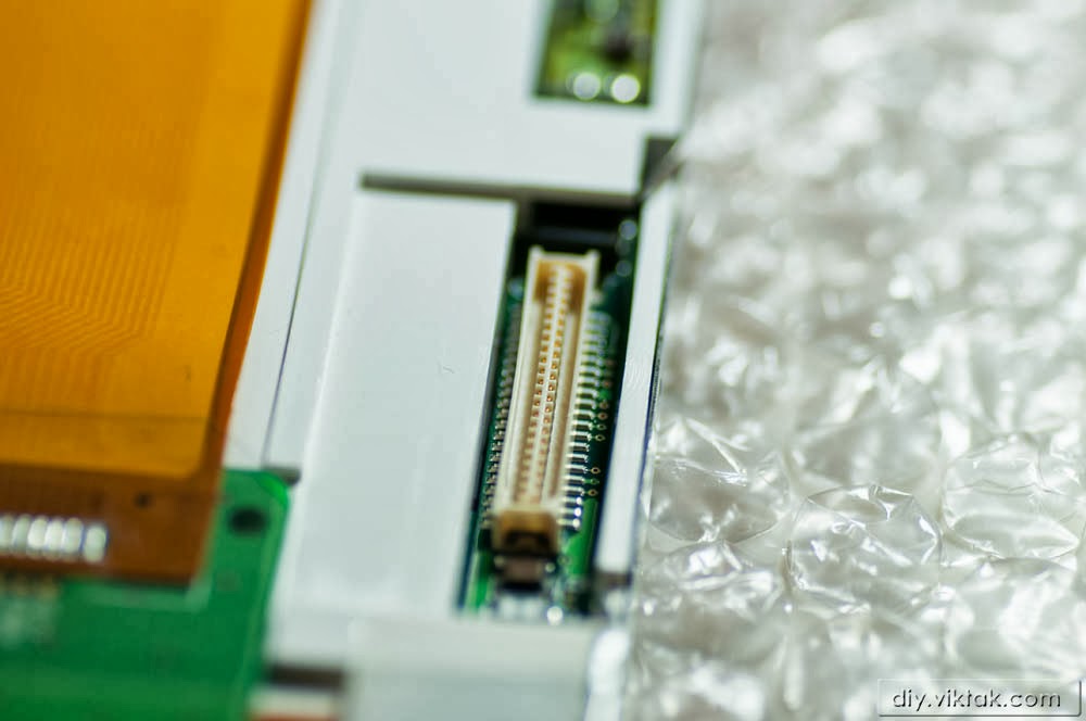 |
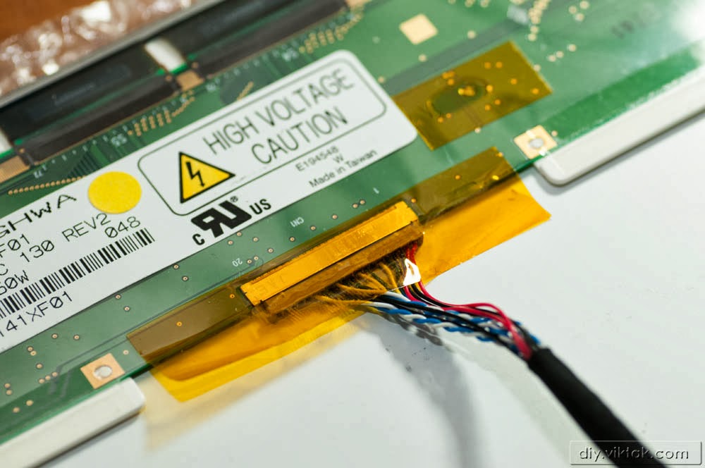
| Some LCD panels have this kind of socket for the cable from the driver board… |
 |
| … they need this kind of connector from the driver board. Note that this connector is polarized, so it’s easy to find out its orientation. |
Once there is only one pair of (usually red and white) cable sticking out of the LCD panel’s side and nothing else, it is probably ready to receive the new inverter and driver boards.
First attach the connector from the driver board. Pin #1 is marked on both the connector and the receptacle, but neither is very visible, so you have to be alert. Orientation of the connector is critical. Attaching the connector the wrong way almost certainly guarantees to kill the LCD panel. The receptacle may break as well, if a connector is forced into it the wrong way.
 |
| The cable from the new driver board attached. |
Next step is to attach the backlight cables (usually red and white cables ending in a two-pin polarized socket on the side of the panel) to the inverter.
 |
| The connector fits snugly in its socket on the inverter board. It only fits one way, don’t force it the other way. |
The final step is to double-check everything went well; there is no room for error. It’s a good idea to go through the setup with a multimeter and check if all the grounds are connected, all the power lines are connected, these two are not shorted, etc.
Once everything checks out, connect a supported video source and a power supply to the driver board. It is recommended to use a high quality power supply of 12V DC with a minimum of 4A rating to get the screen going. The same seller sells suitable power supplies, but I happened to have a couple of 12V 15A power supplies which I could use to test these setups.
Results
If all goes well, you can see the LCD come to life like this:
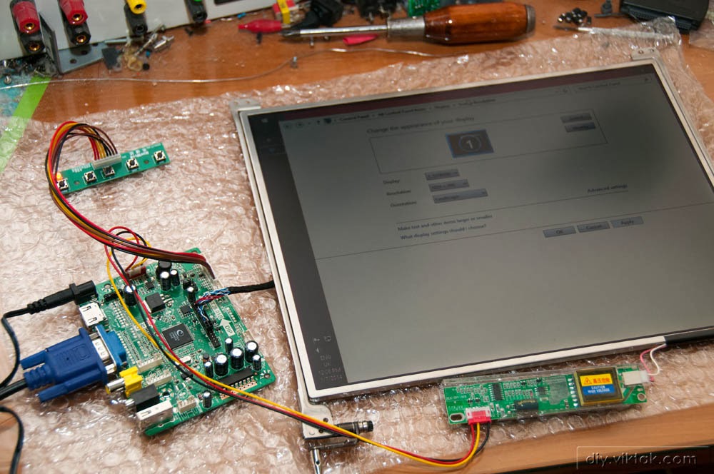 |
| Selecting screen resolution on a Windows 8.1 computer. |
… or, if Raspberry Pi is your fancy, like this:
 |
| Default screen on a Raspberry Pi. |
Last words
These cheap driver / inverter board combos are a great way to give your old LCD screens a new life. They come in many flavours allowing you to use a wide range of resolutions, screen sizes, and video sources.
Hooking up all the cables and boards from such a kit takes a few minutes only and doesn’t really require any specialized skills (apart from being very careful with the delicate parts that break easily). Not even soldering is required.
